Beijing RichAuto S&T Co., Ltd.
56
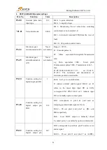
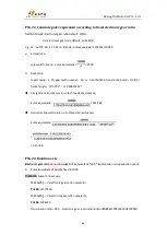
DO5
andALRM- respectively.
Bit2
:
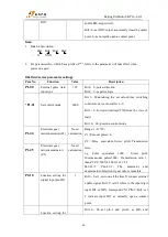
0--set DO5 output as normally closed b-contact
point, 1--as normally open a-contact point.
Note:
1.
Data bit description:
…
Bit3 Bit2 Bit1 Bit0
…
X XXX
2.
For parameters No. which has a prefix of "*", refers to the parameter will take effect when
power on again.
DELTA A2 series parameter settings
Para No.
Function
Value
Description
P1-00
External pulse train
input type
102
Bit 0
:
2--pulse+direction
Bit 2
:
1--negative logic
*P1-01
Set control mode
0000
Bit 3
:
Maintaining the set value.Since switching
control mode is not used,bit 3--0.
Bit 2
:
0--forward rotation(CCW)(from the view of
load)
Bit 1,0
:
00--position control mode
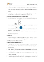
P1-44
Electronic gear
ratio(numerator)(Z1)
Need
calculation
Range
:
1~32767
;
Z1 =Encoder pulses×4
;
Z2 =Pulse equivalent×Screw pitch×Transmission
ratio
e.g. Pulse equivalent 1000
,
Screw pitch
10mm,encoder pulses5000
,
Transmission ratio 1,
then Z1/Z2=5000×4/1000×10×1=2/1.
Pn1-44=2,
Pn1-45=1;
The
numerator
and
denominator of electronic gear ratio is reducible.
P1-45
Electronic gear
ratio(denominator)
(Z2)
Need
calculation
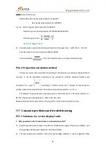
P2-10
Function setting for
digital input pin DI1
1
Bit 0
:
Set 1,servo on all the time.If connect external
enable signal: Bit1,0: set 01 refers to the input digit
input DI1 as SON, correspond CN1 PIN-9; Bit2: set
1 indicate input DI1 as normally open a-contact
point.
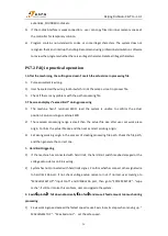
Function setting for
Bit1,0
:
08--set pin-1 and pin-26 as BK- and


