


Beijing RichAuto S&T Co., Ltd.
20
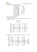
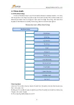
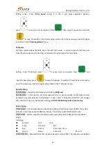
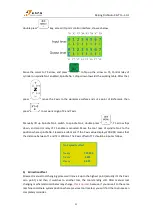
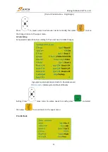
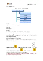
Setting
:
Press “
”move to left or right in the row. Press “
”can jump up and down.
Move the cursor to arrow which needs flip, and press “
” to flip the arrow.
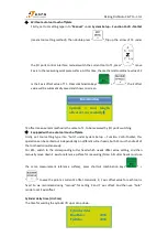
C.A.D. Thickness (Unit: mm)
The thickness should input actual value. If the input value is bigger than the actual thickness, Z
axis may over cut; if smaller, Z axis tool bit can’t reach workpiece surface. This parameter can only
take effect when user uses auto tool setting function. Invalid when manual set workpiece origin
(press XY
→0, Z→0
)
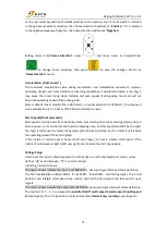
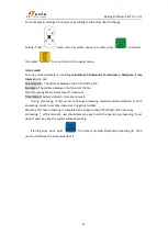
Max Spd Limit (Unit: mm/min)
Set the maximum movement speed of three axis positive and negative direction, the setting is
only effect during processing, not affect the speed in manual mode;
System defaults max. speed X+/-,Y+/-are60000000 mm/min, Z+ is 1800mm/min, Z-is 3000
mm/min.
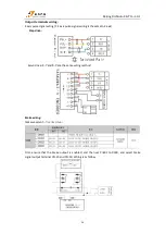
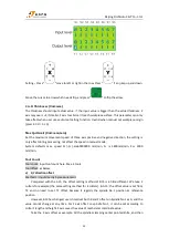
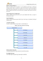
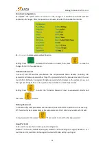
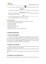
Tool Count
Tool count: Input tool count here. Max. 4 tools.
Tool offset: as below,
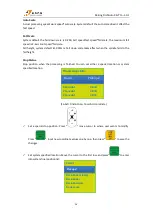
a)
X,Y direction offset
Method 1: Input directly by measurement
Compared with the A15, the offset setting method of B15 is a little different. We take 2
cutters for example (the same setting method for 4 cutters). In A15, the offset value is set from
T2 and no need to set T1 offset, because it regards the spindle No.1 position as reference
position.
However, B15 has changed, user should set both X and Y offset on Spindle No.1 as 0, and the
value cannot change at any time. For Z axis offset on spindle No.1, it can be set according to
cutter’s length and height.
Z axis saves the value of mechanical coordinate value.
Take the X axis offset as example. All the spindles clamping center pointed knife, and then