


Appendix
45
9.0
Appendix
9.1
Troubleshooting
The following section provides information to assist
for troubleshooting or repairing the
iQUBE
.
Materials needed to accomplish these steps are:
•
Revolution III
loaded onto a laptop PC. If using
Virtui
,
iRev
must be loaded on the PC
•
Digital voltmeter
9.1.1
General Steps
To determine that the
iQUBE
has power, check LED
D1 on the core module and LEDs for the load cells
assigned on each connector board (see Figure 2-2 on
page 4). If no load cell LEDs (D18–D25) are on,
download configuration to the
iQUBE
.
Use a voltmeter to measure the voltage at connector
J10. Pin 1 should show 6 volts.
Verify communication LEDs D5 and D6 on the core
module are flashing (see Figure 2-2 on page 4). If
both LEDs are not flashing, check wiring and setup.
For
Virtui
applications, if the power and the LEDs are
all properly lit, use the
Diagnostic
softkey to go into
diagnostic mode. (This feature can be enabled in the
Feature menu in Config mode.) Use the diagnostic
displays to view the outputs of each load cell.
If no
Virtui
is available, connect the PC running
Revolution III
to connector J7 with switch 6 in the off
position. After connecting, upload the
iQUBE
c o n f i g u r a t i o n t o t h e P C t o v e r i f y t h e p r o p e r
configuration is still loaded. If not, download the
correct configuration to the
iQUBE
and recalibrate.
Also verify that the
iQUBE
software is the latest
version.
If the configuration looks good, check the outputs of
each load cell. Cell outputs should change when a
weight on top of each cell or when the load cell cable
is disconnected.
Use the interactive menu of
Revolution III
to monitor
the cells, platforms, or systems. If any of the load cells
reads incorrectly, correct the problem then test the
total system again.
If these steps does not resolve the problem, contact
Rice Lake Weighing Systems technical support for
further assistance.
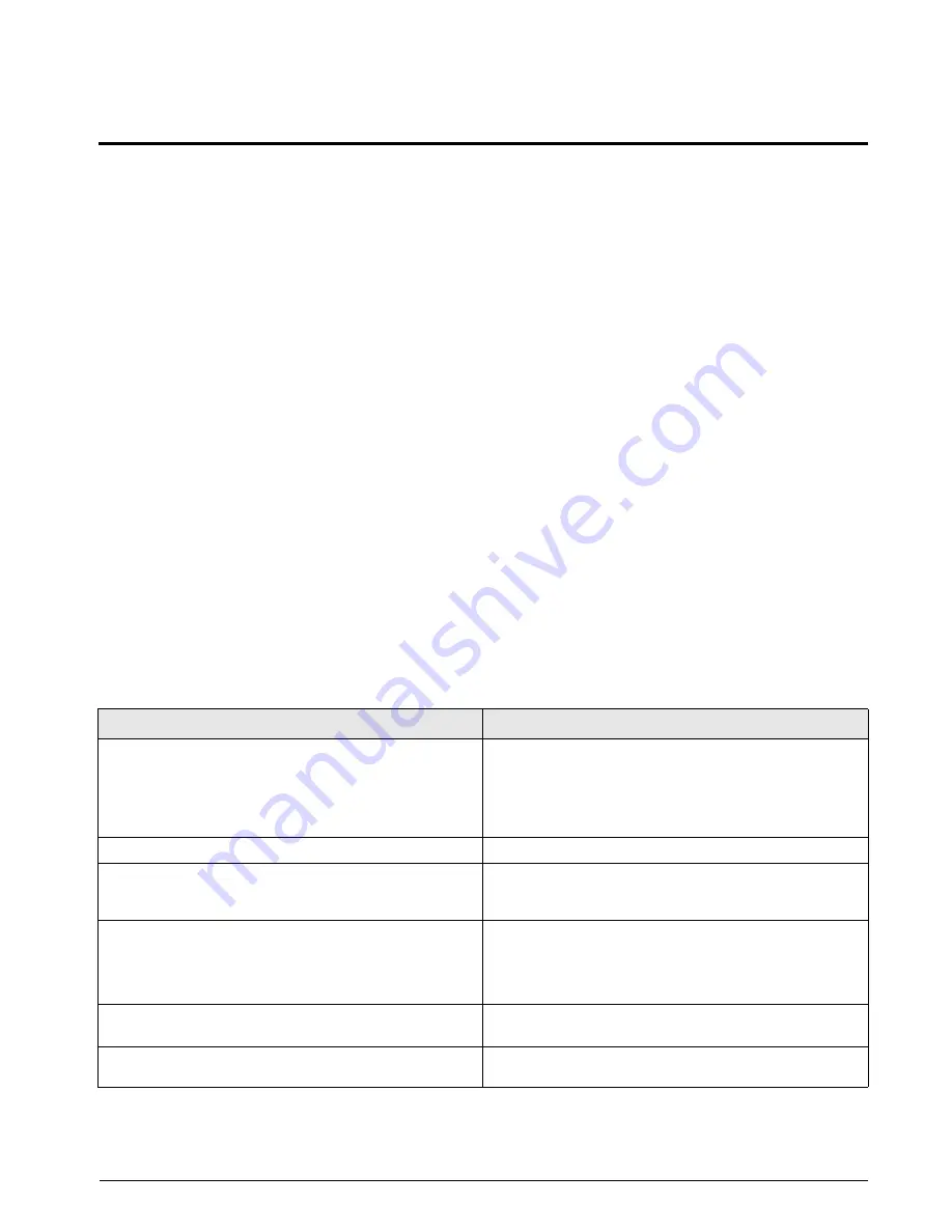
Symptom
Cause/Remedy
iQUBE
seems dead
Verify power indicator LED on connector board is green.
Cycle power by pulling the
iQUBE
fuse and watch D1 on
core module cycle through red, green, then off. If it does not,
turn all switches off and only turn on 8. Cycle power again.
This will clear the core module.
No LEDs lit for load cells
Download from
Virtui
required after setup is completed.
Some LEDs lit green or red
Green light means good config and good cell; red indicates a
load cell fault or bad A/D conversion. Swap load cell cable to
another position.
No scale or
iQUBE
in
Virtui
configuration
Configuration setup and download needed to setup
configuration the
iQUBE
.
Ensure setup switch (DIP switch 4 on the core module) is ON
to enable download from
Virtui
to
iQUBE
.
Print button causes drift
Change print format in PFORMT to send print to a port not
connected to the
iQUBE
.
Slaves not configured
Cycle power on primary unit only. Secondary units will receive
new configuration data.
Table 9-1.
iQUBE
Troubleshooting


