


30
iQUBE
Installation Manual
Platforms field. Click the
Platform 1
box to
assign Platform 1 to System 1. Use the
G e n e r a l d i s p l a y t o e n t e r s c a l e s y s t e m
parameters.
4.1.2
Downloading to the iQUBE
Once configuration is complete, you must download
the configuration data from the PC to the
iQUBE
.
1. Go to the Communications menu and select
Connect…
Revolution automatically detects
the
iQUBE
communications port.
2. Return to the Communications menu and
select
Download Configuration
. Click
Begin
to
initiate the download. Downloading may take
up to 30 seconds.
4.2
Using iRev
The
iRev
utility provides a suite of functions used to
support configuration, calibration, customization, and
backup of the
920i
software. Hardware and software
configuration,
920i
display setup for up to ten screen
designs, stream and ticket formatting, setpoint
configuration, database management, and
iRite
program editing are all supported by
iRev
.
Calibration values, scale, setpoint, and display
configuration, database tables, and user programs, can
be both saved and restored to the
920i
using
iRev
. Other
supporting applications provided with
iRev
include:
•
The
iRev
Editor provides a basic editor and a
compiler for writing
iRite
applications.
•
The Rice Lake Web Update utility uses your
internet connection to check for and download
updates to the
iRev
and
920i
software.
•
The iLaunch utility can be installed to display a
set of icons used for convenient startup of
iRev
and its supporting applications, including the
Help system.
Hardware and Software Requirements
M i n i m u m s y s t e m r e q u i r e m e n t s : 1 6 6 M H z ,
x
86-compatible, with 32MB RAM (64MB for NT4/
2000), 40MB disk space. Recommended system: 233
MHz,
x
86-compatible or greater, with 64MB RAM,
40 MB disk space.
iRev
runs on most Windows
®
operating systems,
including Windows 95 (original release), Windows 95
OSR2, Windows 98, Windows 98 SE, Windows ME,
Windows NT 4.0 (SP4 or greater), Windows 2000, and
Windows XP (Home or Professional).
When used with the original release of Windows 95,
iRev
requires an updated version of TAPI. The TAPI
update is included on the
iRev
installation CD and is
available from the RLWS web site at
www.rlws.com
.
Internet Explorer
®
(IE) 4.0 or greater is required to use
the
iRev
help system. Explorer is included on the
iRev
installation CD or is available from Microsoft
Corporation.
iRev
is installed using a standard Windows installation
procedure.
iRev
applications and support files are
installed in a directory named iRev; icons for the
iRev
application, the
iRev
Editor, Uninstall,
and the Rice
Lake Web Update utility are placed in the Windows
Start menu.
See the
920i
Installation Manual
for more information
about using
iRev
.
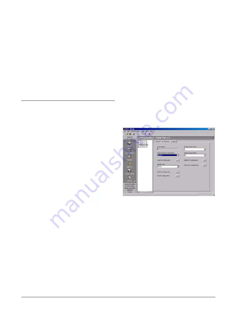
iRev Configuration
Configuration of the
iQUBE
using the
iRev
program is
similar to using the
920i
menus. Use the
Tools
toolbar
selection to configure the serial port used for the
iQUBE
connection.
Figure 4 -2 shows one of the
i Re v
serial port
configuration displays.
Figure 4-2.
iRev
Serial Port Configuration Display
Once
iRev
configuration of the
920i
is complete, use
the
Download Configuration
function on the
iRev
Communications menu to download the configuration
to the indicator.
To download the
920i
configuration to the
iQUBE
, use
the
Download
softkey on the
920i
serial port IQUBE
CONFIG menu. Use the
up
and
down
keys to select
Download iQUBE configuration only
, then press
enter
.
At version 2.05 and higher, the
920i
download to
iQUBE
is done automatically after the
iRev
download.


