


User’s Manual Code 001
Page 9-47
Rev 0819
9
HEAT PUMP COMMISSIONING
The following instructions must be read and understood prior to the commissioning of the
RED Heat Pump. If under any circumstance, there are aspects to the installation and or system
which do not comply with the specification laid down, the Heat Pump MUST NOT be put into
operation until the system and or installation meets all the requirements.
a.
Check the following is complete before commencing the commissioning phase of the
installation.
b.
Check that the correctly rated RCD, power cable and lockable isolator is installed.
c.
Check hydraulic and electrical connections are correct.
d.
Check that cabling has been correctly routed and clamped.
e.
Check the air tightness of the connections.
f.
Check all required valves are open including pump valves.
g.
Check the correctly sized heating expansion vessel has been fitted with 3 bar PRV.
h.
Check compressor bracket has been removed and nothing has been left inside the
heat pump compartment.
i.
Inspect to ensure that all casing components have been refitted correctly.
9.1
Filling the system
The system should have the correct corrosion inhibitor added to the correct volume before
filling with water. The system should be filled cold through a fill loop via a filling loop isolation
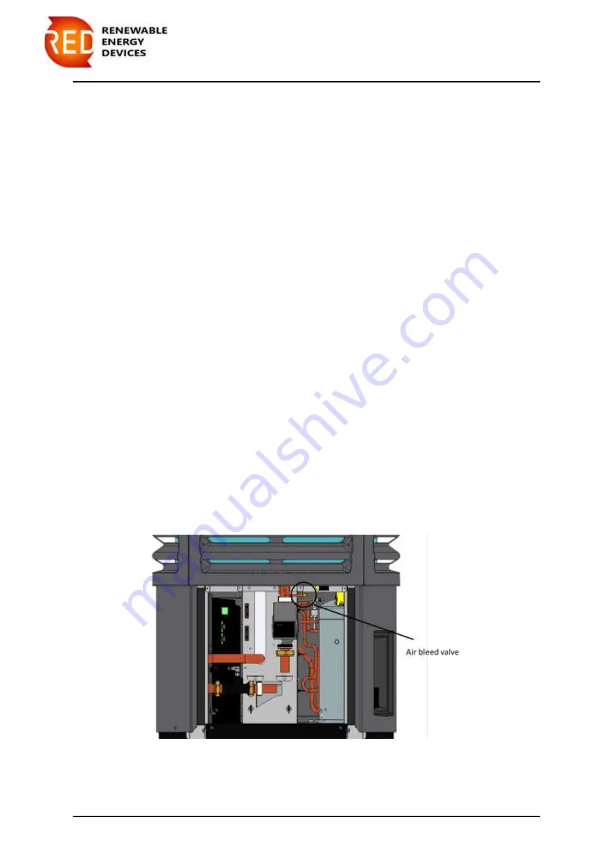
valve. Once the system pressure has reached 1 bar air should begin to dispel through the
system auto air vents. Continue to fill until all air is dispelled. To bleed the heat pump of air
a Schrader bleed valve is located above the circulating pump as shown in Figure 23. By
surpassing the valve air can escape from the heat pump heat exchanger. However please
ensure that the Schrader cap in replaced after bleeding. Once all perceived are has been
removed the circulating pumps can be ran manually to remove trapped air, please see Section
9.1.1. The heat pump will require bleeding again during the running of the circulating pump.
Figure 23 Shrader bleed valve location
Содержание A10-UHE
Страница 2: ......
Страница 15: ...User s Manual Code 001 Page 4 12 Rev 0819 Figure 3 Heat pump and controller dimensions...
Страница 16: ...User s Manual Code 001 Page 4 13 Rev 0819 Figure 4 heat pump assembly drawing...
Страница 17: ...User s Manual Code 001 Page 4 14 Rev 0819 Figure 5 Indoor controller assembly drawing...
Страница 19: ...User s Manual Code 001 Page 4 16 Rev 0819 Figure 7 Distribution manifold configuration...
Страница 21: ...User s Manual Code 001 Page 4 18 Rev 0819 Figure 8 Hot water tank dimensions drawing...
Страница 38: ...User s Manual Code 001 Page 7 35 Rev 0819...
Страница 55: ...User s Manual Code 001 Page 10 52 Rev 0819 Figure 24 Minimum servicing and installation requirements...
Страница 64: ......


