26
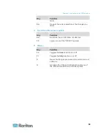
The OSD interface offers these functions:
Channel selection
System configuration
Displaying product information
In This Chapter
OSD Layout............................................................................................. 26
Activating the OSD.................................................................................. 29
Deactivating the OSD ............................................................................. 29
Variations of Highlight Colors.................................................................. 29
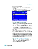
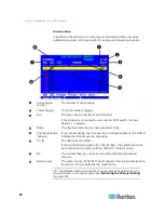
Channel Colors ....................................................................................... 30
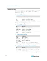
OSD Operation Keys .............................................................................. 32
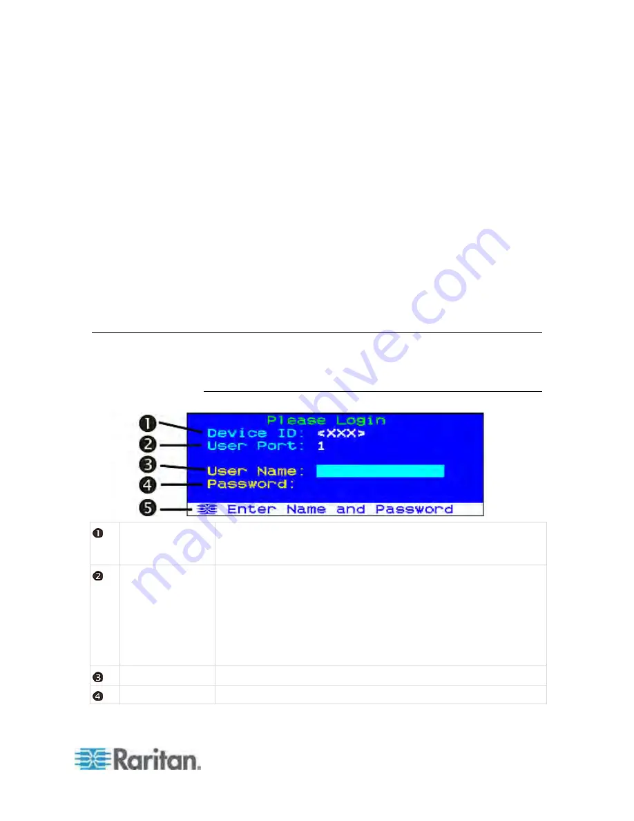
OSD Layout
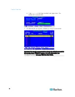
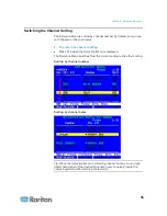
This section indicates the main elements displayed on the OSD images.
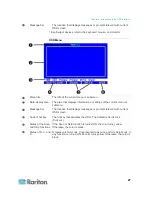
Login Box
Device ID
The name of the TMCAT17 switch that you are operating. Factory
default is the model name. You can customize this name. See
Renaming the TMCAT17 Switch
(on page 44) for more information.
User Port
Current input/output devices* via which you access the TMCAT17
switch and connected computers.
1 refers to the input/output devices directly connected with the
TMCAT17 switch.
2 refers to the input/output devices connected with the MCCAT user
station, which is connected to the
User 2
port of the TMCAT17
switch.
User Name
The field where you type the administrator or user account for login.
Password
The field where you type the password for login.
Chapter 3
Introduction to the OSD Interface
Содержание TMCAT17 series
Страница 11: ...Chapter 1 Introduction 4 MCCAT UST Front and Rear View MCUTP20 PS2 Cable MCUTP20 USB or MCUTP20 SUSB Cable...
Страница 82: ...Appendix A Specifications 75 Screen resolution Refresh rate HZ 1280x1024 60 75 85 1600x1200 60...
Страница 109: ...Index 103 W What are Active and Inactive Channels 5 30 36...

