


DR4300 Owners Manual
System board
130
NOTE:
The maximum output power (shown in watts) is listed on the PSU label.
1. Follow the safety guidelines listed in the Safety instructions section.
2. For systems that support redundant power supply units (PSUs), ensure that both the PSUs are of the same
type and have the same maximum output power
3. If installed, remove the PSU blank.
1. Slide the new PSU into the chassis until the PSU is fully seated and the release latch snaps into place.
NOTE:
If you unlatched the cable management arm, relatch it. For information about the cable
management arm, see the rack documentation of your system.
2. Connect the power cable to the PSU and plug the cable into a power outlet.
CAUTION:
When connecting the power cable, secure the cable with the strap.
NOTE:
When installing, hot swapping, or hot-adding a new PSU, wait for 15 seconds for the system
to recognize the PSU and determine its status. The PSU redundancy may not occur until discovery is
complete. Wait until the new PSU is discovered and enabled before you remove the other PSU. The
PSU status indicator turns green to signify that the PSU is functioning properly.
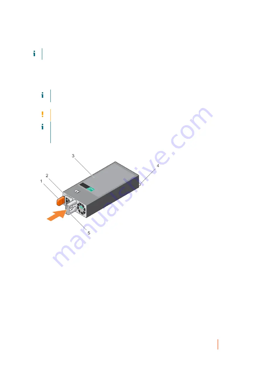
Figure 60. Installing an AC PSU
a. release latch
b. PSU cable connector
c. PSU
d. power connector
e. PSU handle
System board
A system board (also known as the motherboard) is the main printed circuit board found in systems. The
system board allows communication between many of the crucial electronic components of the system, such
as the central processing unit (CPU) and memory, and also provides connectors for other peripherals. Unlike a
backplane, a system board contains significant number of sub-systems such as the processor expansion cards,
and other components.
Содержание DR4300e
Страница 1: ...DR4300e System Owner s Manual ...
Страница 181: ...DR4300 Owners Manual 181 Index ...


