


3 – Managing Fabrics
Displaying Fabric Information
59048-01 A
3-7
3.2.8
Deleting Switches and Links
The SANbox Manager application does not automatically delete switches or links
that have failed or have been physically removed from the Fibre Channel network.
In these cases, you can delete switches and links to bring the display up to date. If
you delete a switch or a link that is still active, the SANbox Manager application
will restore it automatically. You can also refresh the display. To delete a switch
from the topology display, do the following:
1.
Select one or more switches in the topology display.
2.
Open the Switch menu and select Delete.
To delete a link, do the following:
1.
Select one or more links in the topology display.
2.
Open the Switch menu and select Delete.
3.3
Displaying Fabric Information
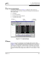
The topology display is your primary tool for monitoring a fabric. The graphics
window of the topology display provides status information for switches, inter-
switch links, and the Ethernet connection to the management workstation.
The data window tabs show name server, switch, and active zone set information.
The Active Zoneset tab shows the zone definitions for the active zone set. Refer
to
”Name Server Data Window” on page 4-2
and
”Switch Data Window” on
page 4-2
for information about the Name Server and Switch data windows.
3.3.1
Fabric Status
The fabric updates the topology and faceplate displays by forwarding changes in
status to the management workstation as they occur. You can allow the fabric to
update the display status, or you can refresh the display at any time. To refresh
the topology display, do one of the following:
■
Choose the Refresh button.
■
Open the View menu and select Refresh.
■
Press the F5 key.
■
Right-click anywhere in the background of the topology display and select
Refresh Fabric from the popup menu.
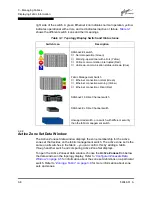
The topology display uses switch and status icons to provide status information
about switches, inter-switch links, and the Ethernet connection. The switch icons
indicate 16 port switch or an unknown switch type. The switch status icons,
displayed on the left side of a switch, vary in shape and color. Switches controlled
by an Ethernet Internet Protocol have a colored Ethernet icon displayed on the
Содержание SANbox2 SANbox2-64
Страница 1: ...S i m p l i f y 59048 01 A Page i SANbox2 64 Switch Management User s Guide...
Страница 36: ...2 Using SANbox Manager Using the Faceplate Display 2 24 59048 01 A Notes...
Страница 62: ...3 Managing Fabrics Zoning a Fabric 3 26 59048 01 A Notes...
Страница 84: ...4 Managing Switches Restoring the Factory Default Configuration 4 22 59048 01 A Notes...
Страница 104: ...6 Managing Ports Testing Ports 6 16 59048 01 A Notes...
Страница 188: ...A Command Line Interface Zoning Command A 84 59048 01 A Notes...
Страница 214: ...C Messages Trap Configuration Dialog C 22 59048 01 A Notes...
Страница 218: ...D Glossary D 4 59048 01 A Notes...


