- 81 -
1100-GB SERVICE_3843
GB
SERVICE
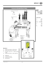
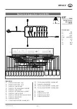
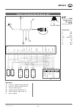
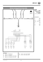
Electrical circuit diagram (Power Control/ISOBUS)
Note!
All plug views are
seen from the
outside.
Explanation:
Y1
Directional control valve - raise
Y2
Directional control valve - lower
Y3
Seat valve - mower unit right
Y6
Seat valve - fill hydraulic pressure relief right
Y5
Seat valve - mower unit left
Y6
Seat valve - fill hydraulic pressure relief left
Y7
Seat valve - mower unit centre
Y8
Seat valve - floating position mower unit centre
Y9
Seat valve - side protection
Y10 Seat valve - interlock
Y11 Cross conveyor belt (QFB) - swivelling (left)
Y12 Cross conveyor belt (QFB) - swivelling (left)
Y27 Seat valve - side protection
Y33 Cross conveyor belt (QFB) - swivelling (right)
Y34 Cross conveyor belt (QFB) - swivelling (right)
S1 Speed
sensor
S3
Position mower unit left
S5
Position mower unit right
S7
Position from mower unit
1
+
UB
2
GND
3
Signal
Colour code:
bl blue
br brown
gn green
gnge green/yellow
gr grey
rt red
sw black
ws white

