


- 25 -
1100_GB-Power-Control_3843
POWER CONTROL - OPERATION
GB
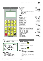
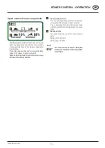
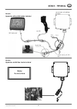
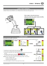
Diagnostic Function
Monitoring of the job computer for
- operating voltage
- sensor supply voltage
- short-circuit to ground or 12 V
- cable break
- overload
Note!
Any desired
function may be
established ma-
nually using the
emergency actua-
tor in the event of
a malfunction (see
Section “Electro-
hydraulics”).
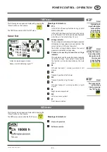
Note!
An error should
be acknowledged
using the “ESC”
key
Note!
The diagnostic
function for every
single channel
can be switched
off until the next
system start using
the “minus” key
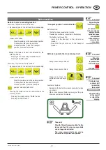
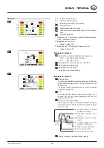
Switching outputs (example: Y1 = raise directional
control valve)
On fault identification
- the alarm screen is faded in and an alarm sound is
audible.
- the corresponding symbol and fault are displayed.
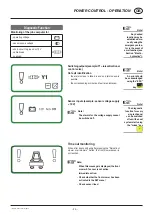
Sensor inputs (example: sensor voltage supply
< 10 V)
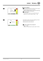
Note!
The alarms for the voltage supply cannot
be switched off.
Time out monitoring
When, after 6 seconds and after pressing the “Raise front
mower or all mowers” button, the front mower sensor is
not reached.
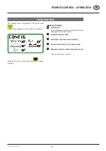
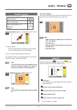
Note:
When
this message is displayed, the front
mower S7 sensor is not active.
Immediate
action:
- Check whether the front mower has been
activated in the SET menu!
- Check sensor lines!


