


- 24 -
1100_GB-Power-Control_3843
POWER CONTROL - OPERATION
GB
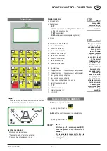
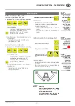
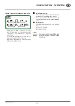
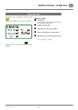
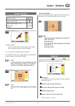
Note!
Altering the respec-
tive configuration
takes place with
the plus and
minus buttons
on the console
Note!
Navigating to
input fields takes
place with the
arrow buttons
on the console
Note!
The menu can be
exited at any
time by pressing
the “I/O” button
The following menu pages are displayed by pressing the
“Menu” button on the console.
The TEST menu comes after the SET menu
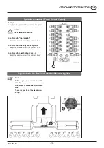
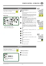
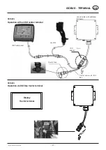
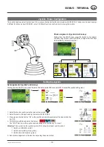
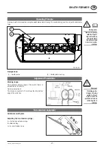
Sensor Test
A black coloured square means:
Sensor / switch delivering signal “1”
TEST menu
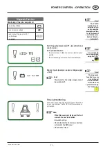
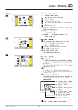
Meanings of Indicators:
a
PTO
In the left field the sensor function during p.t.o still
stand is checked.
In the right field the sensor function during turning
p.t.o is checked. This field has a black background
when the p.t.o turns faster than 10 r.p.m
b
Voltage
indicator
The top voltage indicator shows the lowest measured
distribution voltage value since work started. This
value is stored until the next new start.
The bottom voltage indicator shows the current
measured distribution voltage value.
c
Pressure measuring transmitter voltage
indicator
This indicator shows the current pressure measuring
transmitter voltage level output. Consequently
the function can be checked aided by the data
sheet.
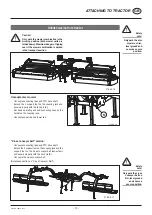
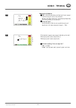
d
S5
Off-road transport / working position of left
mower
e
S15
Transport position of left mower
f
S13
Transport position of right mower
g
S3
Off-road transport / working position o fright
mower
h
S9
Right cross conveyor belt
i
S10
Left cross conveyor belt
j
S7
Front mower position
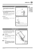
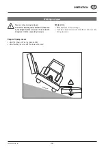
DATA menu
The following menu pages are displayed by pressing the
“Menu” button on the console.
The DATA menu comes after the TEST menu
a
b
Meanings of Indicators:
a
Hours of operation
b
Software
version
a
b
d
c
h
f
g
e
g
i
j


