


9/24
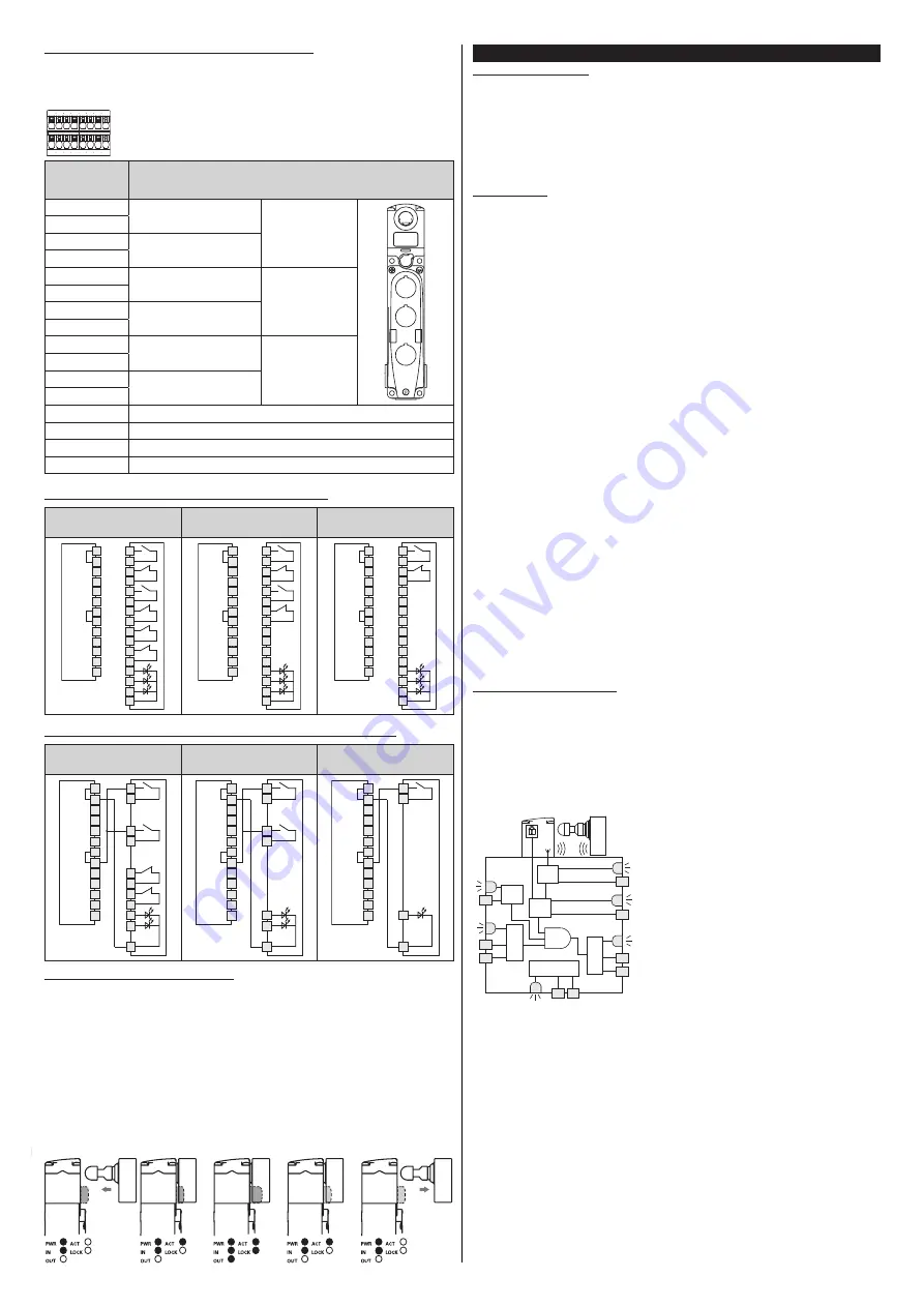
4.10.2 Internal connections of integrated control devices
The switch can be supplied with a cover equipped with between one and three
integrated control devices. The below illustrates the standard connections for these
devices. Other configurations are available on request.
27
28 29 30 31 32 33 34
19
20 21 22 23 24 25 26
Internal terminal
strip integrated
control devices
Connection
19
Contact 1
Device 1
1
2
3
20
21
Contact 2
22
23
Contact 1
Device 2
24
25
Contact 2
26
27
Contact 1
Device 3
28
29
Contact 2
30
31
Supply input +24 Vdc / LED device 1
32
Supply input +24 Vdc / LED device 2
33
Supply input +24 Vdc / LED device 3
34
Supply input 0 V / LED
4.10.3 Switch with integrated field-wireable control devices
NG 2D
••••
1C
NG 2D
••••
1D
NG 2D
••••
1E
NG 2D
••••
1F
NG 2D
••••
1G
NG 2D
••••
1H
15
16
1
2
3
4
5
6
10
11
12
13
14
B2
I4
O3
O4
I3
A1
B1
IS1
IS2
OS1
OS2
A2
I5
19
20
21
22
23
24
25
26
27
28
29
30
31
32
33
34
15
16
1
2
3
4
5
6
10
11
12
13
14
B2
I4
O3
O4
I3
A1
B1
IS1
IS2
OS1
OS2
A2
I5
19
20
21
22
23
24
25
26
27
28
29
30
31
32
33
34
15
16
1
2
3
4
5
6
10
11
12
13
14
B2
I4
O3
O4
I3
A1
B1
IS1
IS2
OS1
OS2
A2
I5
19
20
21
22
23
24
25
26
27
28
29
30
31
32
33
34
4.10.4 Switch with integrated control devices and M23 connector, 19-pole
NG 2D
••••
1C-K603
NG 2D
••••
1D-K603
NG 2D
••••
1E-K602
NG 2D
••••
1F-K602
NG 2D
••••
1G-K601
NG 2D
••••
1H-K601
B2
I4
O3
O4
I3
A1
B1
IS1
IS2
OS1
OS2
A2
I5
4
5
19
19
1
8
9
7
6
6
2
3
12
6
6
19
17
14
15
13
11
10
18
16
1
B2
I4
O3
O4
I3
A1
B1
IS1
IS2
OS1
OS2
A2
I5
4
5
19
19
1
8
9
7
6
6
2
3
12
6
6
19
17
15
18
16
4
5
19
19
1
8
9
7
6
6
2
3
12
B2
I4
O3
O4
I3
A1
B1
IS1
IS2
OS1
OS2
A2
I5
6
17
19
18
4.11 RFID sensor intervention points
The RFID sensor on the device recognises the actuator when placed in front of it.
Within this range the signalling output O3 is activated along with the ACT LED to
indicate the “guard closed” condition. In this condition, it is possible to lock the “guard
closed” state by means of the I4 input. After locking, the LOCK LED and the output
O4 are activated. At the same time the RFID sensor extends its release distance to
prevent vibrations or impacts from causing involuntary opening of outputs OS1, OS2
and O4 when the guard is locked. If the input I4 (or IE1/IE2) is activated or deactivated,
without the actuator present, the device does not lock or activate any of the outputs
OS1, OS2, O4. To open the guard it is necessary to operate via the input I4; with guard
unlocked, output O4 will be deactivated and the LOCK LED will switch off. At this point,
the RFID sensor will reset its operating distance to the initial values and by opening
the guard the output O3 and the ACT LED will be deactivated.
5 OPERATION
5.1 Access monitoring
These devices alone are not sufficient to protect any operators or maintenance
engineers in the event that they are able to physically enter the danger area with their
whole body, since any unintentional closing of a guard behind them could allow the
machine to be restarted. In case the machine restarting control is entirely entrusted
to these switches, a device must be provided to avoid that risk, such as a lock-out/
tag-out system which stops the machine from being restarted. A specifically designed
lock-out/tag-out device is available as an accessory for the switch, which prevents any
unintentional machine start up with the operator still inside. Please contact our sales
offices for more information (see paragraph SUPPORT).
5.2 Definitions
States of the switch:
• OFF: device is off, not powered.
• POWER ON: state immediately following switch on, during which the device carries
out internal tests.
• RUN: state in which the device is working in normal operation.
• ERROR: error state in which the safety outputs are disabled. Indicates presence of a
failure, either internal or external to the device, such as for example:
- a short circuit between the safety outputs (OS1, OS2),
- a short circuit between a safety output and the ground,
- a short circuit between a safety output and the supply voltage,
- an excessive misalignment between the switch and the locked actuator,
- an exceedance of the maximum retention force with failure of the device in locked
condition,
- an exceedance of the maximum or minimum admissible ambient temperature,
- an internal failure.
• The safety functions are defined as follows.
Mode 1:
1.1 The OS safety outputs must be disabled when the actuator is
detected as released.
1.2 The OS safety outputs must be disabled when the actuator is no
longer detected.
1.3 The OS safety outputs must be disabled when at least one of the
safety inputs (IS1 or IS2) is not enabled.
Mode 2:
2.1 The OS safety outputs must be disabled when the actuator is no
longer detected.
2.2 The OS safety outputs must be disabled when at least one of the
safety inputs (IS1 or IS2) is not enabled.
Mode 3:
3.1 The OS1 safety output must be disabled when the actuator is
detected as released.
3.2 The OS2 safety output must be disabled when the actuator is no
longer detected.
3.3 The OS1 safety output must be disabled when the IS1 safety input
is not enabled.
3.4 The OS2 safety output must be deactivated when the IS2 safety
input is not enabled.
With any operation mode the device must keep the guard closed and locked when
the solenoid is enabled (working principle E for versions NG 2D1E••••, NG 2D7E••••)
or disabled (working principle D for versions NG 2D1D••••, NG 2D5D••••, NG
2D6D••••, NG 2D7D••••) and a force less than the declared value F
Zh
is applied.
• The EDM External Device Monitoring function (where present) is a function which
allows the device to monitor the state of external contactors. Activation and deac-
tivation of external contactors must follow the NG switch safety outputs within a
maximum delay.
5.3 Description of operation
Note: the following functional descriptions refer to a device with safety outputs enabled
with guard closed and locked (mode 1).
A device with safety outputs enabled by closing the guard (mode 2) dif-
fers from the above operating mode for the fact that the safety outputs OS1
and OS2 are enabled without the f4 function verifying the guard locking.
Mode 3 differs, in that OS1 is enabled when the guard is closed and locked, and OS2
with guard closed.
Following correct installation in accordance with these instructions, the safety device
can be powered. The diagram below represents the 5 logic functions which interact
inside the safety device.
f4
f1
f2
f3
f0
OS1
OS2
IS2
IS1
IN
O4
PWR
A2
A1
O3
OUT
CODE
ACT
LOCK
I5
EDM
f5
In the initial "POWER ON" state, the safety device
f0 function carries out an internal self diagnosis.
When this terminates successfully, the device
switches to the "RUN" state. If the test is not
passed because of an internal failure, the device
enters the "ERROR" state.
In EDM versions, on power-up, the EDM signal is
checked and must be active within 500 ms from
device start. If the EDM signal is not present, after
the delay time the F5 function sets the device to
the FAULT state.
The "RUN" state is the normal operation state: the
f1 function evaluates the state of inputs IS1, IS2;
at the same time the f2 function checks the pres-
ence of the actuator and the f4 function verifies
that the actuator has been locked.
In the EDM versions the f5 function verifies the
coherence of the EDM signal during state chang-
es and when the safety outputs are off.
When these three conditions are given, the f3 function of the device enables the safety
outputs OS1 and OS2.
The device inputs IS1 and IS2 are normally activated simultaneously and so are
monitored both for state and coherence. In the event of deactivation of just one of
the two inputs, the device deactivates the safety outputs and signals a non-coherent
condition of the inputs via the IN LED flashing green/orange. In order to reactivate
the safety outputs, both inputs have to be deactivated and subsequently reactivated.
In the RUN state, function f0 carries out internal test cycles in order to identify any
failures. Detection of any internal error switches the device to the "ERROR" state
(PWR LED continuously red) which deactivates immediately the safety outputs.
The "ERROR" state can be reached also where short-circuits between the safety
outputs (OS1, OS2), or a short circuit of an output towards ground or towards the
supply voltage, are identified. In this case also, the F3 function deactivates the safety
outputs and the error state is indicated by the OUT LED flashing red.
The O3 signalling output activates during the "RUN" state, at the actuator insertion
into the device, independently of the state of the IS1 and IS2 inputs. The state of this
output is displayed via the ACT LED.
The O4 signalling output activates during the "RUN" state, when the actuator has
been introduced and locked into the device, independently of the state of the IS1 and
IS2 inputs. The state of this output is displayed via the LOCK LED.
The actuator lock or release command is transmitted to the device through the I4
input.