5.2.5.3
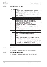
PNU 1302: motion task type
Bit
Value
Meaning
0
0
The position value (Subindex 1) that is given is evaluated as an absolute position.
1
The position value that is given is evaluated as a relative traversing distance.
The two following bits then determine the type of relative motion.
1
0
If Bit 1and Bit 2 are set to 0 and Bit 0 set to 1, then the relative motion task is performed
according to the “InPosition” bit.
1
The new target position is given by the old target position plus the traversing distance.
Bit 1 has priority over Bit 2.
2
0
If Bit 1and Bit 2 are set to 0 and Bit 0 set to 1, then the relative motion task is performed
according to the “InPosition” bit.
1
The new target position is given by the actual position plus the traversing distance.
3
0
no following task available
1
There is a following task, but it must be defined through Subindex 0AH.
4
0
Change over to next motion task, with braking to 0 at the target position.
1
Change over to next motion task, without standstill at the target position.
The type of velocity transition is determined by Bit 8.
5
0
Change over to next motion task, without evaluating inputs.
1
A following motion task is started by a correspondingly configured input.
6
0
Start the next motion task by Input State = low or if bit 7 = 1after the delay set in
PNU 1309.
1
Start the next motion task by Input State = high or if bit 7 = 1after the delay set in
PNU 1309.
7
0
The next motion task is started immediately.
1
The next motion task is started after the delay time set by PNU 1309 or, if Bit 6 = 1, previ-
ously by a corresponding input signal.
8
0
Only for following motion tasks and Bit 4 = 1: from the target position for the previous mo-
tion task onwards, the velocity is altered to the value for the following motion task.
1
The change of velocity is made so that the velocity at the target position of the previous
motion task matches the value given for the following motion task.
9
-
reserved
10
11
12
0
Accelerations are calculated according to the run-up/acceleration and run-down/braking
times for the motion task.
1
the deceleration/aceleration ramps are interpreted in mm/s²
13
0
The target position and target velocity of a motion task are interpreted as increments.
1
The target position and target velocity are recalculated as increments before the start of
the motion task. The parameters PGEARI and PGEARO are used for this purpose.
14
0
The programmed velocity is used as the velocity for the motion task.
1
The velocity for the motion task is determined by the voltage present on analog input SW1
at the start of the motion task.
15
-
reserved
5.2.5.4
PNU 1304: acceleration time
This parameter defines the total time to reach the target velocity for the motion task.
5.2.5.5
PNU 1305: deceleration time
This parameter defines the total time to reduce the velocity to 0 at the target position.
Page 28
User manual PROFIBUS DP PMCtendo DD4
5 Using the parameter channel
Содержание Motion Control PMC
Страница 1: ...Motion Control PMC User manual Item No 21 522 02 Communication profile PROFIBUS DP for PMCtendo DD4 ...
Страница 8: ...This page is deliberately left blank Page 8 User manual PROFIBUS DP PMCtendo DD4 ...
Страница 10: ...This page is deliberately left blank Page 10 User manual PROFIBUS DP PMCtendo DD4 2 Important ...
Страница 14: ...This page is deliberately left blank Page 14 User manual PROFIBUS DP PMCtendo DD4 3 Installation Setup ...
Страница 44: ...This page is deliberately left blank Page 44 User manual PROFIBUS DP PMCtendo DD4 6 Process data channel ...
Страница 62: ...21 522 02 2005 10 Printed in Germany ...


