5.2.3
General parameters
5.2.3.1
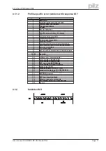
PNU 1000: instrument ID
The instrument ID consists of four ASCII characters, with the contents “S6xx”, whereby xx stands
for the current level of the output stage (e.g. S606).
5.2.3.2
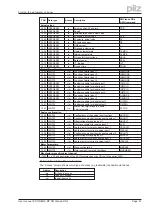
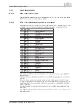
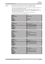
PNU 1001: manufacturer-specific error register
The assignment of the error register can be seen in the following table. The explanation of the indi-
vidual errors can be found in the assembly & installation instructions for the servo amplifier.
Bit
Description
0
Error F01:
Heatsink temperature
1
Error F02:
Overvoltage
2
Error F03:
Contouring error only with SERCOS
3
Error F04*:
Feedback
4
Error F05:
Undervoltage
5
Error F06*:
Motor temperature
6
Error F07*:
Auxiliary voltage
7
Error F08:
Overspeed
8
Error F09*:
EEPROM
9
Error F10*:
Flash-EEPROM
10
Error F11*:
Brake
11
Error F12*:
Motor phase
12
Error F13:
Internal temperature
13
Error F14*:
Output stage
14
Error F15:
I²t max.
15
Error F16:
Mains supply-BTB
16
Error F17*:
A/D-converter
17
Error F18*:
Ballast
18
Error F19:
Mains supply phase
19
Error F20*:
Slot error
20
Error F21*:
Handling error, plug-in card
21
Error F22:
Erdschluss
22
Error F23:
CAN-Bus off
23
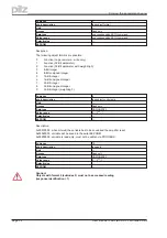
Error F24:
Warning
24
Error F25:
Commuation error
25
Error F26:
Limit switch
26
Error F27:
AS-Option
27-30 Error F28 - F31*:
reserved
31
Error F32*:
System error
When the cause of the error has been cleared, the error state can be canceled by setting Bit 7 in
the control word.
The error response of the PMCtendo DD4 to the reset will differ, depending on the error that has
occurred:
For errors that are marked by an asterisk, setting the reset bit initiates a cold-start of the drive,
whereby the PROFIBUS communication to this instrument will also be interrupted for several sec-
onds. Depending on the circumstances, this break in communication may have to be separately
handled by the PLC.
For the other errors, the reset leads to a warm start, during which the communication will not be
interrupted.
A description of the individual errors and recommendations for removing them can be found in the
installation manual.
User manual PROFIBUS DP PMCtendo DD4
Page 25
5 Using the parameter channel
Содержание Motion Control PMC
Страница 1: ...Motion Control PMC User manual Item No 21 522 02 Communication profile PROFIBUS DP for PMCtendo DD4 ...
Страница 8: ...This page is deliberately left blank Page 8 User manual PROFIBUS DP PMCtendo DD4 ...
Страница 10: ...This page is deliberately left blank Page 10 User manual PROFIBUS DP PMCtendo DD4 2 Important ...
Страница 14: ...This page is deliberately left blank Page 14 User manual PROFIBUS DP PMCtendo DD4 3 Installation Setup ...
Страница 44: ...This page is deliberately left blank Page 44 User manual PROFIBUS DP PMCtendo DD4 6 Process data channel ...
Страница 62: ...21 522 02 2005 10 Printed in Germany ...


