background image


Install 


Installation and 

operating 

instruction 


RuralECO 

Содержание RuralECO 230V

Страница 1: ...Install Installation and operating instruction RuralECO ...

Страница 2: ...ation of hydraulic part 9 8 2 Correct refilling of the heating system 9 9 ELECTRICAL CONNECTIONS 9 9 1 General Information 9 9 2 Supply 10 9 3 Power supply connections 10 9 4 Wiring diagram of interface 12 9 5 Terminal allocation of interface CP022 and heating circuit module IM110 13 10 OPERATION AND DISPLAY 14 10 1 User level 14 10 2 Display and operating elements 14 10 3 Visibility 15 11 OPERATI...

Страница 3: ...ONING 39 15 1 Commissioning AP420 39 15 2 Commissioning OI420 39 15 3 Setup assistant 40 15 4 Set up of heating generator and heat distributing 43 16 MANUAL MODE 44 16 1 Testing of the sensors and actuators with manual mode 44 17 ALARMS AND EVENTS 45 18 WEB APPLICATION 60 18 1 Tested platforms and web browsers 60 18 2 Connection PC to operating unit 60 18 3 Connection smart phone to operating unit...

Страница 4: ...cross and slotted screwdrivers Side cutter Scissors 1 set of wrenches or pipe wrenches Ladder Plumbing material for sealing the threads Equipment for electrical connections Protective gloves Tester and current tongs 2 General Information The RuralECO heat pump is a series of machines full inverter that is with high performance components and widely dimensioned to privilege the efficiency of the ma...

Страница 5: ...uits Works on the heat pump can be done only by authorized and competent people of the customer care 4 Safety information Observe the following points to ensure the reliable safe and trouble free operation of the heating heat pump Installation and initial operation of the heat pump system is restricted to the experts of PicoEnergy and its partners Before starting work disconnect the power supply t...

Страница 6: ... devices The application limits for the individual heat pump types can be found in the respective technical data sheet The RuralECO heat pump is equipped with a safety pressure switch that stop the operation of the machine when a pressure of 4 2 MPa 42 bar is reached The heat pump is equipped with a frost protection system which prevents freezing of the water pipes connected to the heat pump at lo...

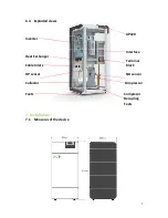
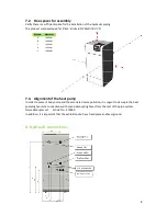
Страница 7: ... 6 3 Exploded views AP420 Inverter Interface Heat Exchanger Terminal Cable Inlets block HP sensor ND sensor Collector Compressor Feets Compresor Decupling Feets 7 Installation 7 1 Measures of the device ...

Страница 8: ... pump In order to prevent body noise and the associated noise pollution it is urgent to decouple the heat pumping hydraulic connections with sound decoupling hoses from the rest of the pipe system Noise decoupler set Article No 670060 In addition it is important that the exhibition site has a fixed place and level ground 8 Hydraulic connections Distance Measures A 400mm B 400mm C 200mm D 600mm E 4...

Страница 9: ...em During the operation of the heat pump system a pressure drop in the heating system can occur The reason is often leaking air that has not been removed completely at the initial operation If the pressure of the heating system falls under 1 5 bar replenishment is necessary IMPORTANT The replenishment must be done exclusively with treated heating water The treatment must be carried out according t...

Страница 10: ...ine to the internal terminal block according to the scheme shown below The cable routing occurs through the special holes as shown in the previous schemes APPROXIMATE section of cables and internal protection 9 3 Power supply connections Get access to the terminal block inside the unit by removing the frontplate of the case Now insert the cables to the inlets 1 at the backplate of the case and con...

Страница 11: ...11 Connect the main power supply for RuralECO 400V units according to the following wiring diagram Connect the main power supply for RuralECO 230V units according to the following wiring diagram ...

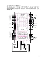
Страница 12: ... be delivered with all plugs The connection plugs are included in the different additional parts packages for example heat pressure switch but can be ordered seperatly at PicoEnergy For more details have a look at the electrical connection diagram for this heat pump type ...

Страница 13: ...m V1 17 Vortex GW demand heating from V1 17 1 DO 230 V pump HC3 DHW circ Pump Changeover valve HC heating cooling Changeover valve HC heating cooling 2 DO 230 V mixer HC2 mixer HC2 Changeover valve passive cooling Changeover valve passive cooling 230VAC IN3 L N supply 230VAC L supply 230VAC L supply 230VAC L supply 230VAC L 1 DO 230 V pump HC2 pump HC2 pump HC2 DHW circ Pump 2 DO 230 V mixer HC1 m...

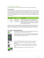
Страница 14: ...are Service technician password required All different user levels are equal with respect to the operating concept and interface display For the login of the additional modes 2 3 see Device If the Service Technician user level is active and the operating unit is not operated for 30 minutes the system will automatically reset to the Easy mode 10 2 Display and operating elements Status light This di...

Страница 15: ...c input panel Here the entered text is displayed on the editing line and after completed confirmation by pressing OK the value from the editing line is accepted and carried over Switching to the key layout with additional character is carried out with ALT Numeric input fields are associated with the numeric input panel The value range within which an entry is possible is displayed below the editin...

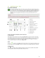
Страница 16: ... 22 C the actually desired daytime temperature can be adjusted directly on the mask Home in the range from 17 C to 27 C This adjustment of the temperature on the mask Home does not change the normally set daytime nominal temperature on the mask heating circuit Alerts The icon signalizes on the Home mask that some alarms in their respective submask are due By selecting this Icon the mask Alerts is ...

Страница 17: ...ting times individually based on the day of the week Night Activation of the operating mode Night decrease mode Standby Turning the currently selected heating circuit on and off For a deactivated heating circuit the frost protection function remains active 11 2 Mask settings In addition to the selection masks of the different system operating modes and the heating circuit operating types that can ...

Страница 18: ...ified through the right selection dial The daytime temperature will now be held constant until that time After that the heating circuit returns to the original operating mode again Time switch The following mask supports the setting of the heating cooling circuit for each individual day of the week or for a group of days The weekday selection can be carried out on the initially displayed Week time...

Страница 19: ... Timer switch Its functionality is analog to its functionality for the heating circuits 11 6 Vacation Allows the one time temporary adjustment of the temperature settings for a time span of several days without changing the normally used daytime and nighttime temperatures Use the selection dials to enter a start date from and an end date to of the vacation time period The vacation time frame there...

Страница 20: ...ch only have one type of temperature distribution circuits heating or cooling and one type of buffer heating or cooling These system mode is also activated automatically in case of performed settings on the option masks of the system This modified settings will be accepted when switching to an active system operating mode again 11 8 Chimney Sweeper This mask is used to start the chimney sweeper mo...

Страница 21: ... screen 11 10 Mask help By clicking on the help button an online window with the operating manual opens The text of the help differs from mask to mask At detail menu masks the help of each single parameter is listed whereas at all other masks a description of the mask and its handling is displayed Submenu Description Service By entering or an incorrect password you exit the Expert mode again and r...

Страница 22: ...me Call Mask Home Detail menu Call the first level of the Detail menu Help Call Mask Help for information concerning the current mask Menu back Revert to previous mask 12 2 Alarms Currently pending alarms that were triggered by the control are administrated on the alarm mask with a descriptive title When an alarm is selected the detail mask with status alarm ID time of occurrence and alarm text of...

Страница 23: ...ervice Provision of the functions required for the service such as e g status report update software save load parameters A specially prepared USB stick is required to carry out some of the service functions included herein e g update software USB data logging which must be inserted into the operating unit an USB stick can either be prepared as update stick or as diagnosis stick 12 5 Save Load par...

Страница 24: ...rating mode manually Load parameter template Save parameter template Detail Menu Service Parameters Load parameter template Detail Menu Service Parameters Save parameter template Parameter Component determines the type of the component that should be stored or loaded Together with the component type parameter Number determines the specific system module Information It is possible to save two backu...

Страница 25: ...ver and the remaining input lines will be deactivated IP Address Indication of the IP address for the visualization communication as well as the corresponding subnet mask and the standard gateway Subnet mask Gateway The settings will finally be accepted by pressing APPLY Below of APPLY the MAC address of the LAN interface is displayed necessary for possible IT unlocks Wireless LAN These mask offer...

Страница 26: ...server a so called VPN tunnel has been established or not To finish the configuration of the mask Remote maintenance the Device name and the Password of the device which are defined in the Remote maintenance VPN server must be entered via alphanummeric panels 12 8 Restart Selecting this parameter initiates a restart After confirming the appearing message window the restart is performed 12 9 Data l...

Страница 27: ...e and transmitted to an USB stick or a PC for further analysis During the generation of the status report an activity bar is displayed During that time the system should not be turned off After the generation the status report needs to be transferred to a plugged in USB stick Via Copy to USB all existing reports will be copied Information In the web application of the visualization Copy to USB is ...

Страница 28: ...n To use the functions of this mask Remote maintenance must be active existing internet connection required The type of the transmission of the message is set via modus Recipient specifies the receiver of the notification It is important to be sure that the phone number always starts with a Language determines in which language the messages will be sent English will be used as the default language...

Страница 29: ... the operating unit 3 Save the parameters see Save Load parameters 4 Restart the system or select Start update on mask Software update to start the update This may take several minutes 5 During the subsequent start up all I O devices are updated if necessary Finally the system starts and the updated visualization software will be displayed Now it is allowed to remove the USB stick that was used fo...

Страница 30: ...2 months a month 4 5 calendar weeks 512 MB flash a week 7 days A line chart supports zoom levels for a year 12 months a month 4 5 calendar weeks a week 7 days a day 24 hours When the chart area gets clicked a tip regarding the respective values of the single data sources will be shown Chart configuration The configuration mask lists all available data sources which can be added to the chart by act...

Страница 31: ...ma takes place by confirming the line System scheme and entering the number of the desired schema shortcuts Definition of terms FU Function unit N A Not available T1 Flow temperature of heat generator T2 Reflux temperature of heat generator T3 Exterior temperature T4 Heat buffer temperature top T5 Heat buffer temperature bottom T7 Hot water temperature tank x T8 Cold buffer temperature top T9 Cold...

Страница 32: ... external heat generator This scheme can also be used for a buffer tank with fresh water module System schema 3 Without buffer A hydraulic separator exists Other modules optional When the number of heat generators of the system is 0 the heating is carried out via an external heat generator Module min number max number Heat generator 0 4 Buffer 0 0 Heating circuit 0 8 Hot water tank 0 4 Solar circu...

Страница 33: ...ixed heating circuit and optionally a hot water tank connected via switching valve System schema 7 Each circuit has its own switching valve for selection of a heat cold generator One collective switching valve for all circuits The external heat request requests from buffer Module min number max number Heat generator 0 4 Buffer 1 1 Heating circuit 0 8 Hot water tank 1 1 Solar circuit 0 4 Ext heat s...

Страница 34: ...request 0 1 System schema 10 Heat cooling source buffer tank with integrated hot water tank cold buffer tank and optionally an external heat source external heat request switching valve for buffer and heating cooling circuits In heating mode the heat buffer is loaded in the cooling mode the cooling buffer Each circuit has its own switching valve It could also have one collective switching valve fo...

Страница 35: ...A heat exchanger is present for passive cooling Each circuit has its own switching valve It could also have one for all circuits This scheme can also be used for a buffer tank with fresh water module when a zone change is available via a valve The fresh water module has no influence on the control of the heating system The external heat request requests from the buffer tank System schema 12 The in...

Страница 36: ...fer is loaded in the cooling mode the cooling buffer Each circuit has its own switching valve It could also have one for all This scheme can also be used for a buffer tank with fresh water module when a zone change is available via a valve The fresh water module has no direct influence on the control of the heating system The external heat request requests from the heat buffer Module min number ma...

Страница 37: ...tion pump can be placed after the buffer tank The external heat request requests from the heat buffer tank System schema 20 2 switch valves switch between hat water tank direct unmixed heating cooling circuit and buffer tank Further heating cooling circuits with circulation pump can be placed after the buffer tank The external heat request requests from the heat buffer tank Module min number max n...

Страница 38: ...mitted at this system schema System schema 53 Each circuit has its own switching valve and could also have one for all circuits This scheme can also be used for a buffer with fresh water module The external heat request requests from the buffer The condenser is located in the buffer Therefore the pump as well as the flow and reflux temperature sensors of the heat generator can be omitted at this s...

Страница 39: ... can be ordered at PicoEnergy 15 1 Commissioning AP420 Detail Menu Service Stationsettings Mask is not available in the web application The mask is used for precise specification of the existing station operating unit With Systemname a unique name for the master operating unit can be set via an alphanumeric input panel Touch remote controls have to assign the same systemname as their master operat...

Страница 40: ... Then the standard layout appears again In the delivery condition or respectively during the loading of the factory settings no type is loaded by default However the parameters are set with default values which represent a heat generator with a small heating power 10 kW To start the operation of the heat generating system proceed as follows 1 Detail menu Put in the Service Technician password If t...

Страница 41: ...ch to ON as well On the following screen you can fix the speed controls of the compressor Just change values if absolutely necessary 6 Heat pump 1 Energy meter Change values if the listed meters are installed The choosen settings are required if PicoEnergy meters are installed Wrong values could cause errors 7 Heat pump 1 Energy meter Change values into the displayed if a PicoEnergy heat meter is ...

Страница 42: ...eather compensation with an mixed heating circuit for heating and cooling At the following screen you can adjust the parameters and the heating curve if required Those specific screens depends on the different schematics 12 Hot water tank Options If an DHW tank is included into the schematic you can specify the options at this screen The following screen is responsible for the main temperatures of...

Страница 43: ...t up of heating generator and heat distributing Detail menu System Options System configuration means that you can choose the quantity of your hydraulic parts All other menu points are responsible for detailed settings 16 For the settings of the heating circuits use the following guidelines see chapter 11 4 17 For the settings of the screed drying use the following guidelines System Parameter Scre...

Страница 44: ...sors and actuators with manual mode 1 Detail menu System Manual mode Manual mode activated via ON OFF switch If activated all relays are turned off and the icon will appear on the status bar 2 Heating circuits Heating circuits 1 4 Return to the previous screen and enter Heat circuits Mixer nominal value push the slider CLOSED OFF OPEN to see if the mixer settings changes 3 If successful return to ...

Страница 45: ...ing and problem solution Depending on the function unit alarms warnings and information are allocated to a certain range of numbers the alarm list is divided accordingly which are 00 49 PLC system alarms 50 99 Detailed information 100 199 Heating system alarms 500 549 Buffer tank alarms 550 599 Hot water tank alarms 600 699 Heating circuit alarms 700 799 Solar circuit alarms 800 849 External heat ...

Страница 46: ...power supply of the affected IO module No 24 Warning Communication error Digital remote control The communication to the digital remote control has been aborted The digital remote control can no longer be used to enter any input Check the bus connection bus address power supply of the affected digital remote control No 25 Warning Communication error Touch remote control The communication to the re...

Страница 47: ...ing power supply and bus connection no 34 Error Communication error Frequency converter Power The communication to the listed module has been aborted Functional units based on this module are not operating Check bus connection bus address power supply of the affected IO module no 35 Error Power malfunction Frequency converter has malfunction Functional units based on this module are not operating ...

Страница 48: ...tor has an error 66 Info Actuator excess power The power monitoring system of the actuator has detected that the power limit has been exceeded 67 Info Actuator insufficient power The power monitoring system of the actuator has detected that the power limit has been undercut 68 Info Actuator group error Error monitoring has detected an error 70 Info Self test failed The self test of the unit has fa...

Страница 49: ...on for the calculation of the inflow temperature of the heating circuits The exterior temperature sensor or its wiring must be checked No 105 Warning Flow temperature sensor The inflow temperature sensor of the heating system is defective If possible the temperature of the heat generating system or the temperature of the external heat source will be used as an inflow temperature The inflow tempera...

Страница 50: ...ring startup Photovoltaic is not active Check and adept parameterization Restart system Yes 500 Warning Frost protection active The frost monitoring system has detected an insufficient water temperature below the frost protection limit A heat request is triggered No 501 Warning Frost protection alarm The frost monitoring system has detected an insufficient water temperature below the frost protect...

Страница 51: ...low the frost protection alarm limit The hot water tank is at risk to be damaged by frost Primarily look at the other alarms These are probably the cause of the standstill of the system A rectification of those should also cancel the frost protection alarm If this does not fix the alarm please contact customer service immediately Yes 560 Warning Sensor top temperature The top temperature sensor of...

Страница 52: ...on The hot water tank auxiliary heater and its wiring has to be checked No 569 Warning Hot water tank leg timeout Legionella disinfection time out Broken temperature sensor or hot water tank didn t got hot Check why the top temperature didn t get high enough Yes 600 Warning Frost protection active The frost monitoring system has detected an insufficient inflow water temperature below the frost pro...

Страница 53: ...ng was found during the start up process The heating circuit is not active Check and correct assigned parameters Restart system Yes 615 Warning Screed Drying Screed drying settings have to be checked before resuming Screed drying is not started until confirmation Confirm message Yes 616 Warning Sensor room humidity The humidity room sensor is defect Cooling function is deactivated The humidity roo...

Страница 54: ... consumer has exceeded the maximum temperature set in the parameters The heat request is withdrawn Wait until the temperature has fallen No 709 Error Sensor reference temperature The reference temperature sensor of the solar consumer is defective Solar consumer is not ready for operation The sensor or its wiring must be checked No 710 Warning Heat meter The inflow or reflux temperature sensor or t...

Страница 55: ...e sensor of the external heat source or its wiring must be checked No 861 Error Ext heat source The digital output to request the external heat source is defective The external heat source cannot be requested The digital output or its wiring must be checked No 862 Error Ext heat source The analog output to request the external heat source is defective The external heat source cannot be requested T...

Страница 56: ... and will be turned off The temperature sensor or its wiring must be checked No 100 5 Error Max compressor out temperature Maximum temperature compressor output exceeded The heat pump is not ready for operation and will be turned off The heat pump can only be reactivated when the temperature at the compressor output falls below the parameterized value No 100 6 Error Sensor temperature source in Th...

Страница 57: ...parameterized value No 101 4 Error Sensor low pressure The pressure sensor is defective The heat pump is not ready for operation and will be turned off The pressure sensor or its wiring must be checked No 101 5 Error Low pressure Minimum pressure limit undercut The heat pump is not ready for operation and will be turned off The heat pump can only be reactivated when the pressure rises above the pa...

Страница 58: ... reactivated when the temperature rises above the parameterized value No 102 2 Error Min source out temperature Minimum source input temperature undercut The heat pump is not ready for operation and will be turned off The heat pump can only be reactivated when the temperature rises above the parameterized value No 102 3 Error Min reflux temperature Minimum reflux temperature undercut The heat pump...

Страница 59: ...s 103 1 Error Defrosting Timeout Maximum retry for finishing defrosting reached Heat pump is not operational Check heat pump Yes 103 2 Error Overheat control Overheat control broken Electronic expansion valve stays closed Check sensors and wiring Check parameterization of controller No 103 3 Error Min flow temperature Temperature is below limitation Heat pump is not operational Heat pump is operat...

Страница 60: ...ress line of the Internet browser Upon completed authentication the web application is released for operation and the home mask appears 18 3 Connection smart phone to operating unit Prerequisite WLAN router on the Ethernet of the system Activate WLAN on the smart phone and open your mobile browser and enter the name of your AP 420 e g ap420_0 local or the IP address of your AP 420 e g http 10 150 ...

Страница 61: ...he access datas will be sent to your state e mail address Follow the instructions as shown in the e mail Afterwards you will be taken to the overview screen in which you see the attachments assigned to them Click on the appropriate attachment Click on WebHmi Click on www and get access to the visualisation ...

Страница 62: ... the following points in the operating instructions Important informations and Safety Informations Refrigerant R410A Cleaning and care Operation and Display The operator must also be informed that unauthorised work on the heat pump invalidates the warranty 21 Cleaning and care A periodic maintenance is necessary first of all to keep a correct and efficient operation of the heat pump in order to re...

Страница 63: ...ordance with its design and or its intended purpose 23 Disposal The operator is responsible for proper disposal of the heat pump and all operating fluids and cleaning agents The industry specific and local regulations for the disposal of different materials must be observed The heat pump may only be dismantled and disposed of by qualified personnel The refrigerant must be recycled or disposed of i...

Страница 64: ...ctim may not be aware of asphyxiation Remove victim to uncontaminated area wearing self contained breathing apparatus Keep victim warm and rested Call a doctor Apply artificial respiration if breathing stopped Skin eye contact In case of frostbite spray with water for at least 15 minutes Apply a sterile dressing Immediately flush eyes thoroughly with water for at least 15 minutes Remove contaminat...

Страница 65: ...25 Declaration of Conformity ...

Страница 66: ...PicoEnergy GmbH Co KG Aumühlweg 20 A 4812 Pinsdorf Tel 43 0 7612 20806 www picoenergy at office picoenergy at ...

Отзывы: