36
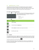
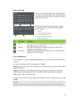
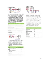
System schema 14
Heat/cooling source, buffer tank, hot water
tank and optionally an external heat source,
external heat request, reversing valve for hot
water load and heating/cooling circuits. Via the
priority of the circuits the operating mode of
the buffer is determined. In heating mode, the
cooling circuits are inactive, in cooling mode,
the heating circuits. In the cooling operation,
the thermal stratification of the buffer can be
changed via a switching valve. The external
heat request requests from the buffer tank.
Module
min. number max. number
Heat generator / Cold generator
0
4
Buffer
1
1
Heating circuit / Cooling circuit
0
8
Hot water tank
1
1
Solar circuit
0
4
Ext. heat source
0
1
Ext. heat request
0
1
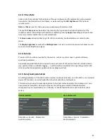
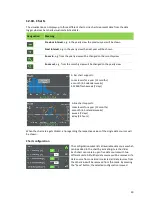
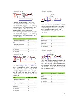
System schema 15
In heating mode, the heat buffer is loaded in
the cooling mode, the cooling buffer. Each
circuit has its own switching valve. It could also
have one for all. This scheme can also be used
for a buffer tank with fresh water module
when a zone change is available via a valve.
The fresh water module has no direct influence
on the control of the heating system. The
external heat request requests from the heat
buffer.
Module
min. number
max. number
Heat generator / Cold
generator
0
4
Buffer
2
2
Heating circuit / Cooling circuit
0
8
Hot water tank
1
1
Solar circuit
0
4
Ext. heat source
0
1
Ext. heat request
0
1
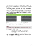
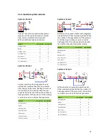
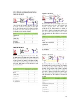
System schema 16
Heat/cooling source, one hot water tank
connected via a switching valve and optionally
an external heat source, external heat request
and at most one unmixed heating/cooling
circuit
Module
min. number max. number
Heat generator / Cold generator
0
4
Buffer
0
0
Heating circuit / Cooling circuit
0
1
Hot water tank
1
1
Solar circuit
0
4
Ext. heat source
0
1
Ext. heat request
0
1

