


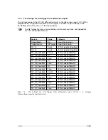


A Pinouts
Pin
I/O Type
Name
Description
1
PWR
CAMERA_GND
Camera GND, 0V
2
PWR
CAMERA_PWR
Camera Power 12V..24V
3
O
ISO_OUT0
Default Strobe out, internally Pulled up to ISO_PWR
with 4k7 Resistor
4
I
ISO_INC0_N
INC0 differential input (G2: RS-422, H2: HTL),
negative polarity
5
I
ISO_INC0_P
INC0 differential input (G2: RS-422, H2: HTL), positive
polarity
6
PWR
ISO_PWR
Power supply 5V..24V for output signals; Do NOT
connect to camera Power
7
I
ISO_IN0
IN0 input signal
8
O
ISO_OUT1 (MISC)
Q1 output from PLC, no Pull up to ISO_PWR ; can be
used as additional output (by adding Pull up) or as
controllable switch (max. 100mA, no capacitive or
inductive load)
9
I
ISO_IN1(Trigger IN)
Default Trigger IN
10
I
ISO_INC1_N
INC1 differential input (G2: RS-422, H2: HTL),
negative polarity
11
I
ISO_INC1_P
INC1 differential input (G2: RS-422, H2: HTL), positive
polarity
12
PWR
ISO_GND
I/O GND, 0V
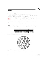
Table A.2: Power supply connector pin assignment
92
Содержание MV1-R1280-50-G2 Camera Series
Страница 6: ...CONTENTS 6...
Страница 10: ...2 Introduction 10...
Страница 14: ...3 How to get started GigE G2 Figure 3 3 PFInstaller components choice 14...
Страница 26: ...4 Product Specification Figure 4 1 Photonfocus MV1 R1280 GigE camera series with C mount lens 26...
Страница 30: ...4 Product Specification 30...
Страница 51: ...Figure 5 19 Crosshairs Example with different grey values 5 6 Crosshairs 51...
Страница 72: ...6 Hardware Interface 72...
Страница 84: ...7 Software 84...
Страница 88: ...9 Warranty 88...
Страница 90: ...10 References 90...
Страница 94: ...B Camera Revisions 94...
Страница 95: ...C Document Revision History Revision Date Changes 1 0 April 2015 First version 95...


