


5.2.4
Exposure Time Control
Depending on the trigger mode, the exposure time can be determined either by the camera or
by the trigger signal itself:
Camera-controlled Exposure time
In this trigger mode the exposure time is defined by the
camera. For an active high trigger signal, the camera starts the exposure with a positive
trigger edge and stops it when the preprogrammed exposure time has elapsed. The
exposure time is defined by the software.
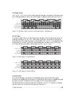
Trigger-controlled Exposure time
In this trigger mode the exposure time is defined by the
pulse width of the trigger pulse. For an active high trigger signal, the camera starts the
exposure with the positive edge of the trigger signal and stops it with the negative edge.
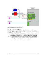
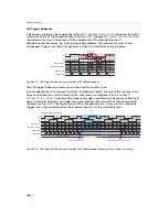
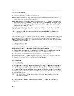
External Trigger with Camera controlled Exposure Time
In the external trigger mode with camera controlled exposure time the rising edge of the
trigger pulse starts the camera states machine, which controls the sensor and optional an
external strobe output. Fig. 5.5 shows the detailed timing diagram for the external trigger
mode with camera controlled exposure time.
e
x t e r n a l t r i g g e r p u l s e i n p u t
t r i g g e r a f t e r i s o l a t o r
t r i g g e r p u l s e i n t e r n a l c a m
e r a c o n t r o l
d e l a y e d t r i g g e r f o r s h u t t e r c o n t r o l
i n t e r n a l s h u t t e r c o n t r o l
d e l a y e d t r i g g e r f o r s t r o b e c o n t r o l
i n t e r n a l s t r o b e c o n t r o l
e x t e r n a l s t r o b e p u l s e o u t p u t
t
d - i s o - i n p u t
t
j i t t e r
t
t r i g g e r - d e l a y
t
e x p o s u r e
t
s t r o b e - d e l a y
t
d - i s o - o u t p u t
t
s t r o b e - d u r a t i o n
t
t r i g g e r - o f f s e t
t
s t r o b e - o f f s e t
Figure 5.5: Timing diagram for the camera controlled exposure time
The rising edge of the trigger signal is detected in the camera control electronic which is
implemented in an FPGA. Before the trigger signal reaches the FPGA it is isolated from the
camera environment to allow robust integration of the camera into the vision system. In the
signal isolator the trigger signal is delayed by time t
d
−
iso
−
input
. This signal is clocked into the
FPGA which leads to a jitter of t
jitter
. The pulse can be delayed by the time t
trigger
−
delay
which
can be configured by a user defined value via camera software. The trigger offset delay
5.2 Trigger and Strobe
37
Содержание MV1-R1280-50-G2 Camera Series
Страница 6: ...CONTENTS 6...
Страница 10: ...2 Introduction 10...
Страница 14: ...3 How to get started GigE G2 Figure 3 3 PFInstaller components choice 14...
Страница 26: ...4 Product Specification Figure 4 1 Photonfocus MV1 R1280 GigE camera series with C mount lens 26...
Страница 30: ...4 Product Specification 30...
Страница 51: ...Figure 5 19 Crosshairs Example with different grey values 5 6 Crosshairs 51...
Страница 72: ...6 Hardware Interface 72...
Страница 84: ...7 Software 84...
Страница 88: ...9 Warranty 88...
Страница 90: ...10 References 90...
Страница 94: ...B Camera Revisions 94...
Страница 95: ...C Document Revision History Revision Date Changes 1 0 April 2015 First version 95...


