


7 Software
7.2.1
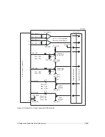
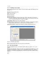
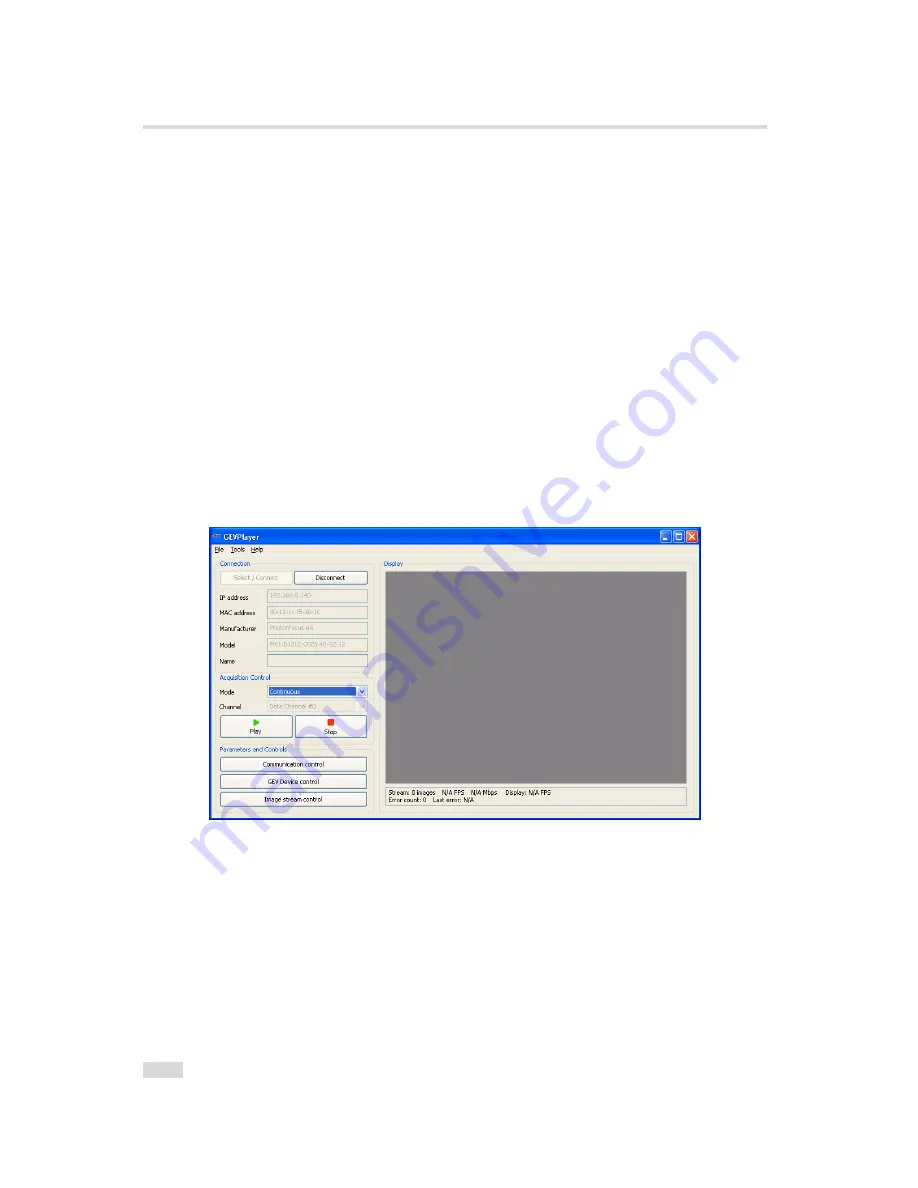
PF_GEVPlayer main window
After connecting the camera (see Chapter 3), the main window displays the following controls
(see Fig. 7.1):
Disconnect
Disconnect the camera
Mode
Acquisition mode
Play
Start acquisition
Stop
Stop acquisition
Acquisition Control Mode
Continuous, Single Frame or Multi Frame modes. The number of
frames that are acquired in Multi Frame mode can be set in the GEV Device Control with
AcquisitionFrameCount
in the
AcquisitionControl
category.
Communication control
Set communication properties.
GEV Device control
Set properties of the camera head, IP properties and properties of the PLC
(Programmable Logic Controller, see also Section 6.6 and document [PLC]).
Image stream control
Set image stream properties and display image stream statistics.
Figure 7.1: PF_GEVPlayer main window
Below the image display there are two lines with status information
7.2.2
GEV Control Windows
This section describes the basic use of the GEV Control windows, e.g. the
GEV Device Control
window.
The view of the properties in the control window can be changed as described below. At start
the properties are grouped in categories which are expanded and whose title is displayed in
bold letters. An overview of the available view controls of the GEV Control windows is shown
in Fig. 7.2.
74
Содержание MV1-R1280-50-G2 Camera Series
Страница 6: ...CONTENTS 6...
Страница 10: ...2 Introduction 10...
Страница 14: ...3 How to get started GigE G2 Figure 3 3 PFInstaller components choice 14...
Страница 26: ...4 Product Specification Figure 4 1 Photonfocus MV1 R1280 GigE camera series with C mount lens 26...
Страница 30: ...4 Product Specification 30...
Страница 51: ...Figure 5 19 Crosshairs Example with different grey values 5 6 Crosshairs 51...
Страница 72: ...6 Hardware Interface 72...
Страница 84: ...7 Software 84...
Страница 88: ...9 Warranty 88...
Страница 90: ...10 References 90...
Страница 94: ...B Camera Revisions 94...
Страница 95: ...C Document Revision History Revision Date Changes 1 0 April 2015 First version 95...


