


6 Hardware Interface
6.5.3
Single-ended Outputs
ISO_OUT0 and ISO_OUT1 are single-ended isolated outputs.
ISO_OUT0 and ISO_OUT1 have different output circuits: ISO_OUT1 doesn’t have
a pullup resistor and can be used as additional Strobe out (by adding Pull up) or
as controllable switch. Maximal ratings that must not be exceeded: voltage: 30
V, current: 0.5 A, power: 0.5 W.
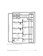
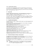
Fig. 6.7 shows the connection from the ISO_OUT0 output to a TTL logic device. PTC is a current
limiting device.
I
S O _ G N D
I S O _ P W
R
P o w e r
M O S F E T
I S O _ O U T 0
P T C
4 k 7
C a m
e r a
3
1 2 p o l . H i r o s e
C o n n e c t o r
I S O _ G N D
1 2
Y O U R _ G N D
I S O _ P W
R
Y O U R _ P W
R
Y O U R _ G N D
C o n t r o l L o g i c
&
Y O U R _ P W
R
+
+
+
+
6
M a x . 3 0 V
M a x . 0 . 5 A
M a x . 0 . 5 W
Figure 6.7: Connection example to ISO_OUT0
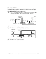
Fig. 6.8 shows the connection from ISO_OUT1 to a TTL logic device. PTC is a current limiting
device.
I
S O _ G N D
P o w e r
M O S F E T
I S O _ O U T 1
P T C
C a m
e r a
8
1 2 p o l . H i r o s e
C o n n e c t o r
I S O _ G N D
1 2
Y O U R _ G N D
Y O U R _ G N D
C o n t r o l L o g i c
&
Y O U R _ P W
R
+
4 k 7
+
Y O U R _ P W
R
M a x . 3 0 V
M a x . 0 . 5 A
M a x . 0 . 5 W
Figure 6.8: Connection from the ISO_OUT1 output to a TTL logic device
.
64
Содержание MV1-R1280-50-G2 Camera Series
Страница 6: ...CONTENTS 6...
Страница 10: ...2 Introduction 10...
Страница 14: ...3 How to get started GigE G2 Figure 3 3 PFInstaller components choice 14...
Страница 26: ...4 Product Specification Figure 4 1 Photonfocus MV1 R1280 GigE camera series with C mount lens 26...
Страница 30: ...4 Product Specification 30...
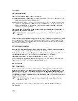
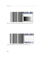
Страница 51: ...Figure 5 19 Crosshairs Example with different grey values 5 6 Crosshairs 51...
Страница 72: ...6 Hardware Interface 72...
Страница 84: ...7 Software 84...
Страница 88: ...9 Warranty 88...
Страница 90: ...10 References 90...
Страница 94: ...B Camera Revisions 94...
Страница 95: ...C Document Revision History Revision Date Changes 1 0 April 2015 First version 95...