


5 Functionality
t
trigger
−
offset
results then from the synchronous design of the FPGA state machines and from to
requirement to start an exposure at a fixed point from the start of the read out of a row. The
exposure time t
exposure
is controlled with an internal exposure time controller.
The trigger pulse from the internal camera control starts also the strobe control state machines.
The strobe can be delayed by t
strobe
−
delay
with an internal counter which can be controlled by
the customer via software settings. The strobe offset delay t
strobe
−
delay
results then from the
synchronous design of the FPGA state machines. A second counter determines the strobe
duration t
strobe
−
duration
(strobe-duration). For a robust system design the strobe output is also
isolated from the camera electronic which leads to an additional delay of t
d
−
iso
−
output
Table 5.3
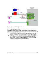
gives an overview over the minimum and maximum values of the parameters.
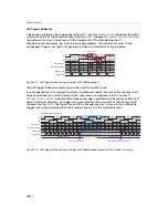
External Trigger with Pulsewidth controlled Exposure Time
In the external trigger mode with Pulsewidth controlled exposure time the rising edge of the
trigger pulse starts the camera states machine, which controls the sensor. The falling edge of
the trigger pulse stops the image acquisition. Additionally the optional external strobe output
is controlled by the rising edge of the trigger pulse. Timing diagram Fig. 5.6 shows the detailed
timing for the external trigger mode with pulse width controlled exposure time.
e
x t e r n a l t r i g g e r p u l s e i n p u t
t r i g g e r a f t e r i s o l a t o r
t r i g g e r p u l s e r i s i n g e d g e c a m
e r a c o n t r o l
d e l a y e d t r i g g e r r i s i n g e d g e f o r s h u t t e r s e t
i n t e r n a l s h u t t e r c o n t r o l
d e l a y e d t r i g g e r f o r s t r o b e c o n t r o l
i n t e r n a l s t r o b e c o n t r o l
e x t e r n a l s t r o b e p u l s e o u t p u t
t
d - i s o - i n p u t
t
j i t t e r
t
t r i g g e r - d e l a y
t
e x p o s u r e
t
s t r o b e - d e l a y
t
d - i s o - o u t p u t
t
s t r o b e - d u r a t i o n
t r i g g e r p u l s e f a l l i n g e d g e c a m
e r a c o n t r o l
d e l a y e d t r i g g e r f a l l i n g e d g e s h u t t e r r e s e t
t
j i t t e r
t
t r i g g e r - d e l a y
t
e x p o s u r e
t
t r i g g e r - o f f s e t
t
s t r o b e - o f f s e t
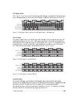
Figure 5.6: Timing diagram for the Pulsewidth controlled exposure time
The timing of the rising edge of the trigger pulse until to the start of exposure and strobe is
equal to the timing of the camera controlled exposure time (see Section 5.2.4). In this mode
however the end of the exposure is controlled by the falling edge of the trigger Pulsewidth:
38
Содержание MV1-R1280-50-G2 Camera Series
Страница 6: ...CONTENTS 6...
Страница 10: ...2 Introduction 10...
Страница 14: ...3 How to get started GigE G2 Figure 3 3 PFInstaller components choice 14...
Страница 26: ...4 Product Specification Figure 4 1 Photonfocus MV1 R1280 GigE camera series with C mount lens 26...
Страница 30: ...4 Product Specification 30...
Страница 51: ...Figure 5 19 Crosshairs Example with different grey values 5 6 Crosshairs 51...
Страница 72: ...6 Hardware Interface 72...
Страница 84: ...7 Software 84...
Страница 88: ...9 Warranty 88...
Страница 90: ...10 References 90...
Страница 94: ...B Camera Revisions 94...
Страница 95: ...C Document Revision History Revision Date Changes 1 0 April 2015 First version 95...


