


6.6
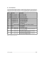
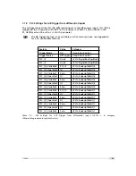
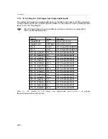
PLC connections
The PLC (Programmable Logic Controller) is a powerful device where some camera inputs and
outputs can be manipulated and software interrupts can be generated. Sample settings and an
introduction to PLC are shown in Section 7.7. PLC is described in detail in the document [PLC].
Name
Direction
Description
A0 (Line0)
Power connector -> PLC
ISO_IN0 input signal
A1(Line1)
Power connector -> PLC
ISO_IN1 input signal
A2 (Line2)
Power connector -> PLC
ISO_INC0 input signal
A3 (Line3)
Power connector -> PLC
ISO_INC1 input signal
A4
camera head -> PLC
FVAL (Frame Valid) signal
A5
camera head -> PLC
LVAL (Line Valid) signal
A6
camera head -> PLC
DVAL (Data Valid) signal
A7
camera head -> PLC
Reserved (CL_SPARE)
Q0
PLC ->
not connected
Q1
PLC -> power connector
ISO_OUT1 output signal (signal is inverted)
Q2
PLC ->
not connected
Q3
PLC ->
not connected
Q4
PLC -> camera head
PLC_Q4 camera trigger
Q5
PLC -> camera head
PLC_Q5 (only available on cameras with Counter
Reset External feature)
Q6
PLC -> camera head
Incremental encoder A signal (only available on
cameras with AB Trigger feature)
Q7
PLC -> camera head
Incremental encoder B signal (only available on
cameras with AB Trigger feature)
Table 6.2: Connections to/from PLC
6.6 PLC connections
71
Содержание MV1-R1280-50-G2 Camera Series
Страница 6: ...CONTENTS 6...
Страница 10: ...2 Introduction 10...
Страница 14: ...3 How to get started GigE G2 Figure 3 3 PFInstaller components choice 14...
Страница 26: ...4 Product Specification Figure 4 1 Photonfocus MV1 R1280 GigE camera series with C mount lens 26...
Страница 30: ...4 Product Specification 30...
Страница 51: ...Figure 5 19 Crosshairs Example with different grey values 5 6 Crosshairs 51...
Страница 72: ...6 Hardware Interface 72...
Страница 84: ...7 Software 84...
Страница 88: ...9 Warranty 88...
Страница 90: ...10 References 90...
Страница 94: ...B Camera Revisions 94...
Страница 95: ...C Document Revision History Revision Date Changes 1 0 April 2015 First version 95...