background image

Safety Tests

Performance Verification

 35

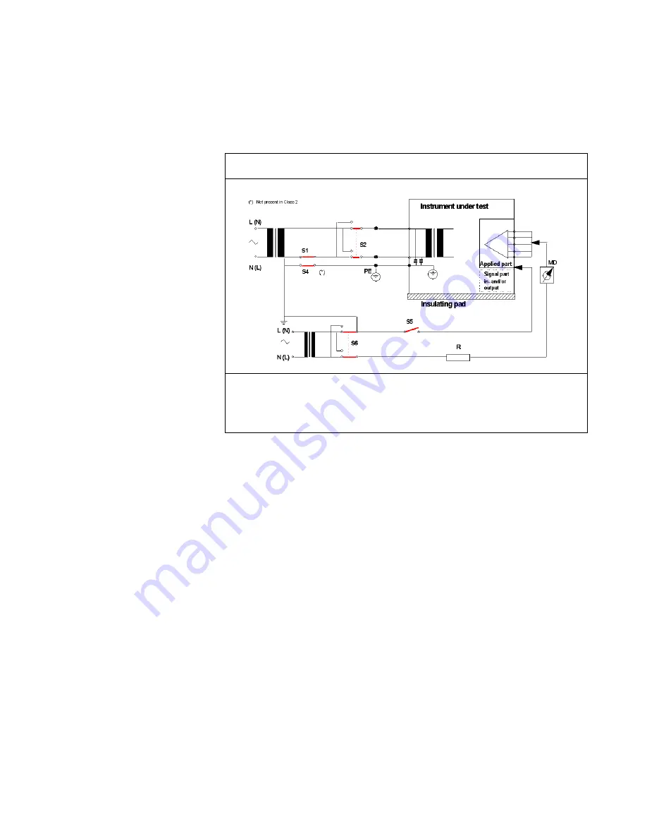
Safety Test Diagram - Patient Leakage Current - AC

Test or Inspection to Perform

Measures patient leakage current from Applied Part to earth caused by external 
mains voltage on Applied Part with switch S5 open and closed. Each polarity 
combination possible is tested using S2 and S6.

Safety test according to EN60601-1 (Clause 19.4.h).

 Report largest value.

Содержание M3921A

Страница 1: ... Number M3921 9000C Printed in the U S A February 2002 First Edition M3921 9000C Philips A1 and A3 Patient Monitors Service Guide A1 Models M3921A M3922A M3923A M3924A A3 Models M3926A M3927A M3928A M3929A ...

Страница 2: ...onsequential damages in connection with the furnishing performance or use of this material Copyright Copyright 2002 Philips Electronics North America Corporation Printing History New editions of this document incorporate all material updated since the previous edition Update packages may be issued between editions and contain replacement and additional pages to be merged by a revision date at the ...

Страница 3: ...s of the Software for archival purposes or when copying or adaptation is an essential step in the authorized Use of the Software You must reproduce all copyright notices in the original Software on all copies or adaptations You may not copy the Software onto any public network No Disassembly or Decryption You may not disassemble or decompile the Software unless Philips prior written consent is obt...

Страница 4: ... as defined in FAR 2 101 a or as Restricted computer software as defined in FAR 52 227 19 Jun 1987 or any equivalent agency regulation or contract clause whichever is applicable You have only those rights provided for such Software and any accompanying documentation by the applicable FAR or DFARS clause or the Philips standard software agreement for the product involved ...

Страница 5: ... or destroy the product or the user s work Warning Warning A Warning calls attention to a condition or possible situation that could cause injury to the user and or patient Explanation of Symbols Symbols on products and packaging mean the following Battery Gauge icon Defibrillator proof type CF equipment On Standby button Alarm Limits icon Adjust Screen Contrast to display monochrome or invert the...

Страница 6: ... Located on recorder Produces a 20 Second Snapshot Located on recorder Produces a Continuous Print Signal ECG Input Signal ECG Output Data input output Alternating Current Direct Current Temperature Humidity Altitude or atmospheric pressure T SpO2 ...

Страница 7: ...must be recycled or dealt wi disposed as chemical waste Fragile handle with care Keep dry Consult instructions for use Date of manufacture Refer to User s Guide DC Lines DC Input Defib Sync RS 232 I O Class II Equipment Power supply if for indoor use only Silence Alarm Equipotential Ground ...

Страница 8: ...About this Manual viii Recorder s front panel charging LED Recorder s front panel communication LED Ground Wire ...

Страница 9: ... 13 Hardware and Software Tests 14 SpO2 Testing 14 Operation with an ECG Simulator 17 Operation with a Respiration Simulator A3 only 18 Verification of Pneumatic System 19 Operation with a Temperature Simulator A1 only 25 Operation with a Temperature Simulator A3 only 25 General Operation 26 Serial Interface Test 26 Printer Verification For A1 Optional Printer M3925A 28 Safety Tests 29 Ground Inte...

Страница 10: ...osed Case Disassembly Procedures 65 Separation of Front and Rear Case Assemblies 68 Front Case Disassembly Procedures 70 Rear Case Disassembly Procedures 75 Main PCB Disassembly Procedures 77 Disassembly Procedures A3 79 Closed Case Disassembly Procedures 79 Separation of Front and Rear Case Assemblies 80 Front Case Disassembly Procedures 82 Rear Case Disassembly Procedures 85 7 Spare Parts 91 Int...

Страница 11: ...ls 118 Optional Materials 118 Overview 119 Support Strategies 120 Unit exchange 120 Bench repair 120 Theory of Operation and System Architecture 121 General 121 System Overview A1 121 Block Diagram A1 121 Block Diagram A1 122 System Overview A3 123 Block Diagram A3 123 Block Diagram A3 124 Troubleshooting 129 Disassembly 130 Monitor Applications and Algorithms 132 Reference Documents and Other Sou...

Страница 12: ...xii Contents ...

Страница 13: ...rred to as the monitor throughout this manual Only where there are differences in service procedures for the two monitor types is each monitor referred to specifically as A1 and A3 Only qualified service personnel should service this product Before servicing the monitor read the User Guide carefully for a thorough understanding of operation ...

Страница 14: ...nd based environments such as ambulances The physical and operational characteristics of the monitor are described in the User Guide The measurement parameters and features for each model are indicated below Model Measurement Parameters and Features NIBP SpO2 Temp ECG Resp Integral Recorder Color Mono A1 Monitor M3921A Yes Yes No No No No Mono M3922A Yes Yes Yes No No No Mono M3923A Yes Yes No Yes...

Страница 15: ... as the A1 monitor the PS 120V or PS 240V The recorder does not have an On Off switch The recorder can sense when it has an established communication link with the monitor At that time the green LINKED indicator on the front panel lights indicating that the recorder is ready for operation See the recorder s User Guide for more information regarding its operation Related Documents To perform test a...

Страница 16: ...Related Documents 4 Introduction ...

Страница 17: ...nd NiBP performance and verification check every two years The following performance verification tests may be used following repair or during routine maintenance if required by your local institution 1 Inspect the exterior of the monitor for damage 2 Inspect labels for legibility If the labels are not legible contact Philips Response Center or your local Philips representative 3 Verify that the N...

Страница 18: ... hour on battery power before the low battery alarm occurs the battery should be conditioned If the same symptom persists even after the battery is conditioned and indicating a full charge the battery should be replaced Refer to Chapter 6 Disassembly Guide Environmental Protection Follow local governing ordinances and recycling plans regarding disposal or recycling batteries and other device compo...

Страница 19: ...s the tests used to verify performance following repairs or during routine maintenance All tests can be performed without removing the covers of the monitor If the monitor fails to perform as specified in any test repairs must correct the problem before the monitor is returned to the user ...

Страница 20: ...laced Power On Test NBP Tests Pneumatic Leakage and Inflation Rate D SpO2 Module replaced Power On Test BPL Test SpO2 Tests Dynamic Operating Range and LED Excitation E Front End Connectors replaced Power On Test BPL Test Performance test for the parameter that had the connector replaced F Power Supply replaced A3 only Power On BPL and Safety tests G Component level repair on any PC board Power On...

Страница 21: ...t approximately 250 mmHg pressure drops no more than 6 mmHg BPL Px6 Where x6 Pressure Drop in mmHg NiBP Accuracy Test 250 mmHg 5 mmHg PN P X1 X4 or X53 PN F X1 X4 or X53 Record Pressure in mmHg X1 3 In the case of the NiBP Deflation Rate Test applicable to the A3 only NiBP Leakage Test After 1 Minute at 250 mmHg pressure drops no more than 6 mmHg Record Pressure Drop in mmHg X2 NiBP Inflation Rate...

Страница 22: ...ve sensor D 25 ECG cable M3913A M3923A and M3924A only ECG electrodes Standard M3923A and M3924A only ECG leads M3914A IEC or M3915A AAMI M3923A and M3924A only NiBP tubing M3918A NiBP cuff 40401C Pulse oximeter tester Nellcor Puritan Bennett SRC 2 ECG simulator Dynatech Nevada medSim 300 or equivalent NiBP simulator Bio Tek BP Pump or equivalent Temperature simulator medSim 300 or equivalent M392...

Страница 23: ...ory set power up defaults If your institution has pre configured custom defaults those values display Battery Charge To fully charge the battery 1 Connect the monitor to an AC power source using the proper power cord For the A1 use the PS 120V or PS 240V external power supply and power cord 2 For the A1 verify that the EXTERNAL POWER indicator is lit For the A3 verify that the BATTERY CHARGING AC ...

Страница 24: ...iBP simulator to simulate a pressure setting of 120 80 mmHg and heart rate of 80 bpm 5 Ensure that the monitor is not connected to AC power 6 With the monitor turned off press the ON STANDBY button and verify that the battery icon appears at the bottom of the display after the power on self test is completed The boxes in the battery icon should all be filled indicating that the battery is charged ...

Страница 25: ... power source For the A1 use the PS 120V or PS 240V power supply and power cord For the A3 use the proper power cord supplied 2 For the A1 verify that the EXTERNAL POWER indicator is lit For the A3 verify that the BATTERY CHARGING AC SOURCE indicator is lit 3 Do not connect any input cables to the monitor 4 Observe the monitor front panel With the monitor off press the ON STANDBY button The monito...

Страница 26: ...ster to the M4787A sensor cable and connect the cable to the monitor 2 Set SRC 2 as follows 3 Press the ON STANDBY button to turn the monitor on 4 After the normal power up sequence verify that the SpO2 display initially Test Applies to Model s SpO2 Testing A1 A3 all models Operation with an ECG Simulator A1 M3923A M3924A A3 all models Operation with a Respiration Simulator A3 all models Verificat...

Страница 27: ... SpO2 and HEART RATE displays flash indicating both parameters have violated the default alarm limits e The heart rate tone is heard For this test the user should set the heart rate tone source to SpO2 from the Heart Rate Menu 7 Press the ALARM SILENCE button on the front panel of the monitor The audible alarm is temporarily silenced 8 Verify the following a The audible alarm remains silenced b Th...

Страница 28: ...reen Dynamic Operating Range The following test sequence verifies proper monitor operation over a range of input signals 1 Connect the pulse oximeter tester to the monitor and turn the monitor on 2 Place the SRC 2 pulse oximeter tester in the RCAL 63 LOCAL mode 3 Set the SRC 2 as indicated in below Verify that the monitor readings are within the indicated tolerances Allow the monitor several secon...

Страница 29: ...or Verify as the LED approaches the optical sensor that the LED intensity decreases 7 Open the sensor and notice that the LED intensity increases 8 Repeat step 6 and the intensity again decreases This variation is an indication that the micro processor is in proper control of LED intensity 9 Turn the monitor off Operation with an ECG Simulator 1 With the monitor off connect the ECG leads to the ap...

Страница 30: ...120 bpm 13 After at least five heartbeats verify that the monitor displays a heart rate of 120 5 bpm 14 Disconnect the LL lead from ECG simulator 15 Verify that the Leads Off alarm message appears three dashes are displayed in HEART RATE display and the low priority audible alarm sounds 16 Reconnect the LL lead to ECG simulator Verify that the Leads Off alarm message no longer appears and audible ...

Страница 31: ...signed to use the Bio Tek BP Pump noninvasive blood pressure simulator any equivalent NiBP simulator with the same internal test volume can be used The internal test volume of the Bio Tek simulator is 250 ml The monitor must be placed in Diagnostic Mode with the NiBP Test screen active for each of the NiBP tests For a detailed explanation of the Diagnostic Mode refer to Chapter 4 Power up Defaults...

Страница 32: ...sure the integrity of the cuff and adapter tubing then test again If the test fails again verify the integrity of all the pneumatic system tubing inside the monitor If the test still does not pass see test map page 8 Each of the tests mentioned below must be performed to verify pneumatic system functionality These tests can be performed individually in any order or sequentially Prior to performing...

Страница 33: ...T button on the simulator until the simulator displays Pressure Source Set Test Pressure 6 Use the UP DOWN buttons on the simulator to adjust for a pressure of 250 mmHg 7 Press the START PUMP button on the simulator The simulator begins to pressurize The current pressure in mmHg is displayed on both the simulator and the monitor displays 8 Allow 15 20 seconds for the pressure to stabilize The pres...

Страница 34: ...doing the following a Press the CONTRAST button on the monitor b Press the ZERO button on the simulator 6 Press the NiBP button on the monitor to activate the pump 7 Hold the NiBP button until the monitor displays a pressure of approximately 250 mmHg 8 Allow 15 20 seconds for the pressure to stabilize 9 Record the pressure displayed on the monitor 10 Start a 1 minute timer 11 After 1 minute again ...

Страница 35: ...NiBP button until the monitor displays a pressure of 280 mmHg then stop the timer The test is successfully completed if the inflation time is between 1 and 6 seconds 3 Press and hold the Heart Rate Tone VOLUME button until the monitor displays a pressure of 0 mmHg Additional NiBP tests can be performed at this time If no further NiBP tests are to be conducted turn the monitor off Normal monitoring...

Страница 36: ...Press and hold the Heart Rate Tone VOLUME button to ensure that the monitor displays a pressure of 0 mmHg Additional NiBP tests can be performed at this time If no further NiBP tests are to be conducted turn the monitor off Normal monitoring operation returns the next time the monitor is turned on Deflation Rate The deflation rate test verifies the deflation rate of the A3 monitor There is no defl...

Страница 37: ... monitoring operation returns the next time the monitor is turned on Operation with a Temperature Simulator A1 only 1 Remove the probe from its holder 2 Insert the calibration key in the temperature input port T on the A1 3 Press the ON STANDBY button to turn the monitor on After the normal power up sequence verify that the temperature reads 36 3 0 1 C or 97 3 0 2 F 4 Turn the monitor off Operatio...

Страница 38: ...d Perform the following procedure to test the serial port voltages The test is qualitative and only verifies that the serial interface port is powered correctly and that the Nurse Call signal is operational The serial connector is a male DB 9 located on the monitor s real panel identified with the RS 232 symbol 1 Turn the monitor on 2 Set up the DMM with the function set to VDC at a range of 10 vo...

Страница 39: ...rarily silence the audible alarm 8 Connect the DMM positive lead to pin 9 and verify the voltage value listed in Table 5 Voltage for pin 9 is that listed for the alarm underway condition Pin Signal Direction Measurement V Min Typical Max 1 not used 0 4 0 0 0 4 2 RXD input 0 4 0 0 0 4 3 TXD output 0 5 9 0 15 0 4 DTR output 5 0 9 0 15 0 5 GND 0 4 0 0 0 4 6 DSR input 0 4 0 0 0 4 7 RTS output 5 0 9 0 ...

Страница 40: ...ate the monitor wheel to highlight the setup icon Press the wheel and ensure Communications Selection is Printer 5 Connect a M4787A sensor extension cable to the monitor Connect an oxygen transducer to the sensor extension cable Attach it to the subject as described in the sensor directions for use 6 Press the ON STANDBY button to turn the monitor on and verify that the monitor is operating 7 The ...

Страница 41: ...ound wire The A3 patient monitor is a Class I device It requires a protective earth ground wire Test requirements differ for Class I and Class II devices Be aware of the differences and use the appropriate test procedure for the monitor in use There are two categories of safety tests n Ground Integrity n Electrical Leakage Ground Integrity Table 6 Ground Integrity Test or Inspection to Perform Exp...

Страница 42: ... Inspection to Perform Measures impedance of Protective Earth PE terminal to all exposed metal parts of IUT which are for safety reasons connected to the Protective Earth PE Max 100 mOhm Test current 25 Amps applied for 5 to 10 seconds We recommend to flex the main cable during the test in order to identify potential bad contact or damage of the earth wire Safety test according to EN60601 1 Clause...

Страница 43: ...the monitor AC plug to the electrical safety analyzer as recommended by the analyzer operating instructions 2 Perform test as recommended by analyzer operating instructions Earth leakage current is measured under various conditions of the AC mains and protective earth conductor For each condition the measured leakage current must not exceed that indicated below Table 7 Earth Leakage Current Values...

Страница 44: ...alyzer operating instructions The analyzer leakage current indication must not exceed the values listed below Connect analyzer test cable to the snap as arrowed or alternatively to the handle fixing screw NOTE do NOT use this snap on the rear of the case or any of the other screws on the rear of the monitor ...

Страница 45: ... analyzer operating instructions Connect the external power supply output cord to the monitor A3 Connect the monitor s AC mains power cord to the analyzer as recommended by analyzer operating instructions 3 Connect the ECG test cable between the ECG connector on the monitor and the appropriate input connector on the analyzer 4 Turn the monitor on 5 Perform the test as recommended by the analyzer o...

Страница 46: ...present on the applied part terminals during this test Exercise caution to avoid electrical shock hazard Table 10 Safety Tests Patient Leakage Current with Mains Voltage on the Applied Part Test Condition Polarity Allowable Leakage Current Max Type CF Normal Normal 10 µA Reversed 10 µA S F C 1 Open Supply A1 Only 1 S F C Single Fault Condition Normal 50 µA Reversed 50 µA S F C 1 Open Earth Ground ...

Страница 47: ...or Inspection to Perform Measures patient leakage current from Applied Part to earth caused by external mains voltage on Applied Part with switch S5 open and closed Each polarity combination possible is tested using S2 and S6 Safety test according to EN60601 1 Clause 19 4 h Report largest value ...

Страница 48: ...Safety Tests 36 Performance Verification ...

Страница 49: ...ociated with normal monitoring operation Use the following procedure to configure the power up default settings for the monitor 1 Set the monitor to normal monitoring mode 2 Adjust each accessible setting on the monitor as desired Note Use the techniques described in the User Guide Such settings include alarm limits choice of display type for the graphic frames and ECG lead select 3 Use the wheel ...

Страница 50: ...ny Access If Make Available is chosen the caregiver may permanently silence the audible alarm for a particular parameter via the Alarm Limits Menu Some institutions may wish to prevent audible alarms from being permanently silenced If so Deny Access should be selected Alarm Suspend Make Available Deny Access If Make Available is chosen the caregiver may invoke the Alarm Suspend Mode by pressing an...

Страница 51: ... effective the next time the monitor is powered up Note Language selection screen upon boot up can be reactivated by following the steps listed in the section Restoring Factory Settings Enter Diagnostic Mode Yes No If Yes is chosen the Power up Defaults Menu is exited and the Diagnostic Menu appears Done When selected the Power up Defaults Menu is immediately exited and the user is instructed to p...

Страница 52: ... Selection of an item in the menu invokes that test or information screen The test and information screens that appear in the Diagnostic menu are as follows n Error Codes n System Information n System A D Values n NiBP Test n Return Error Codes This screen displays the 10 most recent error code types logged by the monitor After 10 error code types have been logged the oldest error code type is del...

Страница 53: ...s been operational This value cannot be reset Note The Monitor On time Backlight On time and Battery Deep Discharge values are stored in nonvolatile memory When a new Main PCB is installed this value is reset to zero Backlight On time Displays the number of hours rounded to the nearest hour that the LCD Backlight has been operational This value can be reset to zero for instance at the time when a ...

Страница 54: ...set to zero Exiting the screen is accomplished in the normal manner by selecting Return System A D Values The System A D screen displays the current value of each analog to digital A D channel in volts Some of the channels are for AC coupled signals such as ECG input so the numbers on the screen are constantly changing when an input signal is present These AC coupled values are shown to give an in...

Страница 55: ... 8 ECG LEAD OFF 8 ECG LEAD OFF 9 TEMP 2 59 TO 93 9 TEMPERATURE 10 ISOLATED VOLTAGE REF 10 ISOLATED VOLTAGE REF 11 ISOLATED VOLTAGE ZERO 11 ISOLATED VOLTAGE ZERO SpO2 S1 S018 SpO2 S1 S018 12 BATTERY VOLTAGE X 0 5 12 BATTERY VOLTAGE X 0 5 13 TEMP PROBE 0 ORAL 1 RECTAL 2 CAL KEY 3 NONE 13 NOT USED 14 3 3 VDC POWER SUPPLY 14 3 3 VDC POWER SUPPLY 15 NiBP VOLTAGE REF X 0 5 15 12 VDC POWER SUPPLY X 0 33 ...

Страница 56: ...pressure is displayed in mmHg The value is updated at the rate of approximately two times per second Proportional Valve The display indicates whether the Display proportional valve is open or closed Safety Valve Display The display indicates whether the safety valve is open or closed Activate Pump For as long as the NiBP Start Stop button is pressed the pump runs If system pressure reaches the har...

Страница 57: ...and remains at maximum as long as the button is pressed Offset Adjust A momentary press of the CONTRAST ADJUST button invokes the zero calibration routine that is performed immediately prior to each blood pressure measurement This routine looks at the pressure in the system and if the pressure is non zero an offset is applied which causes the system pressure to display as zero When in the NiBP Tes...

Страница 58: ...tor powered off simultaneously press the VOLUME and CONTRAST buttons on the front keypad 2 While continuing to press the VOLUME and CONTRAST buttons power up the monitor 3 Continue to keep the VOLUME and CONTRAST buttons depressed until the power up diagnostic sequence is complete When the normal monitoring screen appears release the two buttons ...

Страница 59: ...orm Repairs Only qualified service personnel should open the monitor housing remove and replace components or make adjustments If your medical facility does not have qualified service personnel contact Philips Response Center or your local Philips representative Replacement Level Supported The replacement level supported for this product is to the printed circuit board PCB and major subassembly le...

Страница 60: ...However problems not covered here can be resolved by calling Philips Response Center or your local representative All categories listed above are discussed in the following sections Power The following table lists recommended actions to address A1 power Problem Area Refer To 1 Power No power up Fails power on self test Powers down without apparent cause Power on page 48 2 Error Messages Error Code...

Страница 61: ...d into Main PCB If the connection is good replace the keypad 6 If the problem persists replace main PCB 2 The A1 fails to power up when the ON STANDBY button is pressed with the monitor connected to external power supply 1 Connect the appropriate external power supply PS 120V or PS 240V to the monitor Ensure that the external power supply input is plugged into an operational AC outlet of the appro...

Страница 62: ...F301 located on the Main PCB near the battery cable connector Replace the fuse if necessary 4 If problem persists replace the main PCB Condition Recommended Action 1 The A3 fails to power up when the ON STANDBY button is pressed 1 Ensure power cord is plugged into operational AC outlet of appropriate voltage and frequency Ensure green BATTERY CHARGING AC SOURCE indicator is lit If indicator is not...

Страница 63: ...provides the capability for technicians to print out a copy of the error log Generating an Error Log Printout A1 only 1 Connect the recorder to the monitor and its power supply to an appropriate source Refer to the operator s manual 2 Use the SETUP button and displayed menu to verify that the Recorder mode is the selected option for the Communications Selection item It is the factory set default v...

Страница 64: ...Recommended Action 1 Improper shutdown 1 Cycle power 2 If this error persists return monitor for service 2 NiBP Sensor Error The two pressure system transducers do not agree 1 Check for blocked tubing in the pneumatic system 2 Replace Main PCB 3 NiBP Pressure Violation Error The pressure on the cuff could not be removed by normal means A fault has been detected in the NiBP system that could not be...

Страница 65: ...or is detected on the power up settings region of Flash memory 1 Turn Power Off 2 Turn power back on while pressing both the CONTRAST and VOLUME buttons See Restoring Factory Settings on page 45 Chapter 4 3 All user selections must be restored 4 If error persists replace Main PCB 64 The SpO2 module is sending an error message to the host CPU 1 Cycle power 2 If problem persists replace Main PCB 65 ...

Страница 66: ...wer supply is low 1 Check power supply 2 Replace power supply assembly 7 The measured value of the 12V power supply is high 1 Check power supply 2 Replace power supply assembly 8 The measured value of the 5V power supply is low 1 Check power supply 2 Replace power supply assembly 9 The measured value of the 5V power supply is high 1 Check power supply 2 Replace Main PCB A The measured value of the...

Страница 67: ...e monitor out of service and contact Philips Response Center or your local Philips representative for advice on remedial action 5 If the Error Code screen indicates no previous occurrences of this error the monitor can be returned to service As a reference following lists the general categories for other error codes The error code categories are shown only in hexadecimal format 65 66 MP 205 SpO2 m...

Страница 68: ...14xxxx system software errors A1 only Code hex Explanation Condition Recommended Action 1 The monitor fails to power up when the ON STANDBY button is pressed 1 Take steps as noted in Power on page 48 2 The monitor powers up but some one of the other buttons does not respond 1 Ensure that the keypad is plugged into the Main PCB If the connection is good change the keypad 2 If the problem persists c...

Страница 69: ...d darken the screen 2 A3 Ensure red LED located on the top left corner of the Main PCB is illuminated If the LED is not illuminated the monitor is not in on state follow troubleshooting steps in Power on page 48 3 Ensure that the backlight cable is connected to the Main PCB 4 Ensure that the LCD connector is properly connected to the Main PCB and LCD PCB 5 If problem persists replace Main PCB 6 A3...

Страница 70: ...the Patient Connector PCB 4 If the problem persists replace Main PCB Condition Recommended Action 1 Monitor appears to be operational but physiological values are suspect or nonexistent 1 Replace each patient cable or tubing with a known serviceable cable 2 Ensure internal ECG temperature and SpO2 cables are connected to Main PCB Ensure tubing in pneumatic system are properly connected and NiBP pu...

Страница 71: ...ut paper remains blank when printing should be present 1 Open recorder door and check paper is oriented correctly paper should exit from bottom of roll See User Guide for an illustration of correct paper orientation 2 If problem persists replace recorder Condition Recommended Action ...

Страница 72: ...Troubleshooting Guide 60 Chapter 5 Troubleshooting ...

Страница 73: ...ssembled down to all major component parts including PCBs battery cables function buttons chassis enclosures The following tools are required small medium Phillips head screwdriver needle nose pliers 9 16 inch socket for wheel encoder 3 16 inch socket for rear panel RS 232 connector Warning Before attempting to open or disassemble the monitor disconnect the power supply from the monitor Warning Hi...

Страница 74: ...hat are used to access replaceable parts of the monitor are illustrated in the Disassembly sections which follow These describe and photographically illustrate procedures for disassembling the monitor to enable removal and replacement of suspected defective assemblies components The monitor consists of two main assemblies the front case assembly and the rear case assembly The main PCB assembly is ...

Страница 75: ...1 Use a Phillips head screwdriver to remove the two screws fastening the battery cover to the rear case 2 Remove the battery cover 3 Disconnect the spade terminal connectors from the battery terminals Caution During reassembly pay particular attention to the polarity of the battery cable before reattaching The polarity is marked on the circuit board Red connects to the ve terminal black connects t...

Страница 76: ...e battery cover Procedure to remove the battery from the monitor when a temperature module is installed 1 Use a Phillips head screwdriver to remove the two screws fastening the temperature module housing to the rear case assembly The same screws also hold the battery cover Foot cushions Battery cover For models with temperature module Temp module ...

Страница 77: ...onnectors from the battery terminals Caution During reassembly pay particular attention to the polarity of the battery cable before reattaching The polarity is marked on the circuit board Red connects to the ve terminal black connects to the ve terminal If battery cable polarity is reversed it is likely that circuit damage will occur 6 Remove the battery 7 As required remove the battery cushions o...

Страница 78: ... and rear case assemblies 1 Remove the SpO2 connector hood by squeezing the sides to release the detents holding the hood in place During reassembly the notch on the SpO2 connector hood should be facing down 2 Use a Phillips head screwdriver to remove the four screws fastening together the front and rear case assemblies 3 Separate the main front and rear case assemblies 4 If the rear cover gasket ...

Страница 79: ... sure speaker wire is out of the way Power up the monitor prior to installing the final four screws If the monitor boots properly insert the four screws and proceed to the performance tests 5 Disconnect the ribbon cable and its connector from the PCB assembly 6 Disconnect the battery cable spade terminals from the main PCB assembly If the battery cable is to be removed the cable must also be disco...

Страница 80: ... making the Luer connection This prevents disconnection Front and rear case assemblies are now completely separate from one another Front Case Disassembly Procedures This section describes how to remove replace items from the front case assembly First separate the front and rear assemblies as described in the section Separation of Front and Rear Case Assemblies on page 78 Procedure to remove the m...

Страница 81: ...en replacing the main PCB in the front case assembly press gently into position and feed the ribbon cable through the hole for the wheel 3 Disconnect the backlight keypad speaker connector and wheel ribbon connector During reassembly tuck the speaker cable out of the way There are now three separate items Front case assembly Rear case assembly Main PCB assembly Main PCB assembly Front case assembl...

Страница 82: ...illips head screwdriver to unfasten the four corner screws These screws also hold the LCD assembly in place 2 Remove the display shield 3 Remove the LCD assembly providing access to the display window 4 Remove the display window by carefully prying up one corner and then peeling back Backlight connector Keypad cable and connector Speaker connector Wheel encoder assembly LCD assembly PCB ...

Страница 83: ...stem of the encoder assembly If the wheel is not easily removable by hand a small flat headed screwdriver can be used to gently pry off the wheel If necessary apply some adhesive tape to the front cover and the head of the screwdriver to prevent any damage 2 Use a 9 16 hex socket to unscrew the fastening nut on the outside of the front case The encoder can now be pulled away from the front case Du...

Страница 84: ...keypad is attached with an adhesive to the front panel 1 From the front side of the panel carefully pry up one corner of the keypad from the cover and then peel it away from the cover 2 Carefully thread the cable out through the slot in the cover Spare wheel Keypad integral cable and connector ...

Страница 85: ...llips head screwdriver to remove the two screws holding the rear connector PCB to the rear cover 2 From outside the rear cover use a 3 16 socket driver to remove the two standoff fasteners of the RS 232 connector 3 From inside the rear cover remove the rear connector PCB assembly Procedure to remove NIBP pump 1 Use a Phillips head screwdriver to unfasten the screw holding the clamp to the rear cov...

Страница 86: ...ry one end of the handle 2 When the end of the handle has begun to loosen from the boss use the same technique to begin to pry up the other end 3 Alternately apply this prying action between each end of the handle until the handle is free of the rear case 4 The foot cushions are attached with an adhesive to the bottom surface of the rear cover and can be removed by lifting one end of the foot and ...

Страница 87: ...he main PCB assembly 1 Pull the tubing from the barbed fitting on the rear of the NiBP panel connector 2 Pull the tubing from the fittings on the the pressure sensors and valve Procedure to separate the patient connector PCB assembly from the main PCB assembly 1 Use needle nose pliers or a Tinnerman tool to remove the two Tinnerman fasteners securing the patient connector PCB assembly to the under...

Страница 88: ...iver to remove four screws fastening the two assemblies together Two of the screws are accessible on the face of the connector PCB two are accessible through access holes in the PCB 2 Separate the two assemblies Patient connector PCB assembly Foot of moulded connector panel after removal of Tinnerman nut Main PCB assembly Connector panel Patient connector PCB ...

Страница 89: ... straight back from the monitor The wheel should slip off the encoder shaft 2 If wheel does not move separate front and rear cases as described in Separation of Front and Rear Case Assemblies on page 78 There is a hole in the front cover behind the wheel Insert a small screwdriver blade in the hole and push firmly against the back of the wheel Procedure to remove carrying handle 1 Use screwdriver ...

Страница 90: ...the front and rear cases are separated Separation of Front and Rear Case Assemblies Procedure to separate front and rear case assemblies 1 Remove handle as indicated in procedure on page 77 2 Use screwdriver to remove four screws fastening Rear Case Assembly to Front Case Assembly to Front Case Assembly Retain for reassembly Note that the gasket must be inserted around the top of the rear case bef...

Страница 91: ...e ribbon cable connector from the main PCB 5 Unscrew the NiBP tubing connector from the pump to the main PCB The front and rear case assemblies are now completely separate from one another Main ribbon cable assembly NiBP tubing Connector to recorder PCB when installed SpO2 module ...

Страница 92: ... case rotate the temperature connector counter clockwise to unscrew it from the fastening nut on outside of the front case Disconnect the white cable and move the SpO2 front connector ground cable before attempting to disconnect the temperature connector The encoder assembly unplug the connector from the main PCB Remove the wheel as described in step 1A Use a 9 16 hex socket to unscrew the fasteni...

Страница 93: ...BP front panel fitting 4 The main PCB can now be removed This allows access to the SpO2 front panel connector NiBP fitting and backlight inverter These can be removed by removing the appropriate screws or nuts During reassembly the backlight inverter cable should be wrapped over the screw post See the upper left hand corner of the picture Encoder Switch panel connector NiBP tubing connector SpO2 c...

Страница 94: ... screws around the periphery of the display backplate Retain the fastening screws for reassembly 2 Carefully remove the metal and foil grounding tabs and washer noting their location and orientation for reassembly The display backplate can now be removed 3 Disconnect the backlight connector from the backlight inverter The LCD can now be lifted out of the front bezel assembly For reassembly place t...

Страница 95: ...ve the three screws holding the battery cover plate in place 2 Grasp the strap accessible through the opening in the top foam cover and gently pull the battery from its housing 3 Remove the wire connectors from the battery clips Remember that the red wire is connected to the plus side of the battery pack The indicator is located under the foam piece ...

Страница 96: ... procedure on page 78 3 If a recorder is not installed remove the recorder blanking cover by slipping a small flat blade screwdriver into one of the slots on the blanking cover Use a screwdriver to gently depress the snap tab on the inside of the cover while pulling the cover away from the monitor After the first tab is released repeat the process on the other side of the cover and remove cover 4 ...

Страница 97: ...ct the speaker twisted pair connector from the power supply PCB The speaker is mounted on one side of the battery housing 7 If a recorder is installed disconnect the ribbon cable from the recorder PCB The recorder PCB can be removed by removing the four screws fastening the PCB to the battery housing Screws fastening battery housing ...

Страница 98: ...power supply assembly 1 On the rear panel of the monitor remove the eight screws holding the power supply assembly 2 Carefully lift the power supply assembly from the rear case 3 The power supply assembly can be disassembled into the following elements Power supply PCB NiBP pump Heat sink chassis Main ribbon cable Fuse F1 Fuse F2 Screws fastening the power supply assembly ...

Страница 99: ...Disassembly Procedures A3 Chapter 6 Disassembly Guide 87 NiBP pump assembly Main PCB Main ribbon cable ...

Страница 100: ...Disassembly Procedures A3 88 Chapter 6 Disassembly Guide ...

Страница 101: ...les that follow Item No corresponds to the callout number in Figure 1 through Figure 12 The Page Ref indicates the page number of the relevant disassembly procedures in Chapter 6 Small Parts Kit Most small parts and hardware screws fuses and so forth can be found in the Small Parts Kit Part Number M3921 64102 ...

Страница 102: ...Top Level Assembly 90 Chapter 7 Spare Parts Top Level Assembly Figure 1 A1 Top Level Assembly Drawing 1 of 2 ...

Страница 103: ...Top Level Assembly Chapter 7 Spare Parts 91 Figure 2 A1 Top Level Assembly Drawing 2 of 2 ...

Страница 104: ...with temperature module page 64 3A M3921 60101 Battery page 63 4A M3921 60102 Battery Pads page 64 5A M3922 60200 Temperature Module Housing page 64 6A M3922 60201 Temperature Probe Sensor Switch page 63 7A M3922 60202 Temperature Probe Grommet page 65 8A M3921 60300 SpO2 Connector Hood page 66 M3921 60301 Rear Cover Gasket page 63 9A M3921 60103 Battery Cable page 63 ...

Страница 105: ...Top Level Assembly Chapter 7 Spare Parts 93 Figure 3 A3 Top Level Assembly Drawing ...

Страница 106: ...Top Level Assembly 94 Chapter 7 Spare Parts Item No Part No Description Page Ref All A3 Models 2 M3926 60800 Handle page 77 ...

Страница 107: ...Front Case Assembly Chapter 7 Spare Parts 95 Front Case Assembly Figure 4 A1 Front Case Assembly Drawing 1 of 3 ...

Страница 108: ...Front Case Assembly 96 Chapter 7 Spare Parts Figure 5 A1 Front Case Assembly Drawing 2 of 3 ...

Страница 109: ...3921 60400 Front Cover Assembly with keypad and display window page 70 11A M3921 60401 Display Shield page 70 12A M3921 60402 LCD Assembly page 70 13A M3921 60403 Display Window with gasket page 70 14A M3921 60404 Speaker page 71 15A 15B M3921 60405 Spring Retainer Clip and Pad page 71 16A M3921 60406 Knob page 71 17A M3921 60407 Encoder page 71 18A M3921 60408 Keypad page 72 ...

Страница 110: ...Front Case Assembly 98 Chapter 7 Spare Parts Figure 7 A3 Front Case Assembly Drawing 1 of 2 ...

Страница 111: ...Front Case Assembly Chapter 7 Spare Parts 99 Figure 8 A3 Front Case Assembly Drawing 2 of 2 ...

Страница 112: ...tting and tubing page 81 11 M3926 60401 Cable SpO2 page 80 12 M3926 60304 Switch panel page 82 M3926A M3927A 8 M3926 60500 PCB main new part page 80 8 M3926 68500 PCB main Version 3 0 Exchange part page 80 10 M3926 60303 Inverter backlight page 82 13 M3926 60300 Bezel front page 82 M3928A M3929A 8 M3928 60500 PCB main new part page 80 8 M3928 68500 PCB main Exchange part page 80 10 M3928 60303 Inv...

Страница 113: ...Ref M3921 68500 Rear Connector PCB with ribbon cable exchange page 73 M3921 60500 Rear Connector PCB with ribbon cable new page 73 M3921 60501 Pump Clamp page 73 M3921 60502 Pump Pad page 73 M3921 60503 NiBP Pump Fitting and Tubing page 73 M3921 60505 Foot Cushion page 74 M3921 60506 Handle page 74 ...

Страница 114: ...Rear Case Assembly 102 Chapter 7 Spare Parts Figure 9 A3 Rear Case Assembly Drawing 1 of 3 ...

Страница 115: ...Rear Case Assembly Chapter 7 Spare Parts 103 Figure 10 A3 Rear Case Assembly Drawing 2 of 3 ...

Страница 116: ...Rear Case Assembly 104 Chapter 7 Spare Parts Figure 11 A3 Rear Case Assembly Drawing 3 of 3 ...

Страница 117: ...3 Cable main ribbon page 86 Part No Description Page Ref M3921 68600 Main PCB Model M3921A exchange page 75 M3921 60600 Main PCB Model M3921A new page 75 M3922 68600 Main PCB Models M3922A M3924A exchange page 75 M3922 60600 Main PCB Models M3922A M3924A new page 75 M3923 68600 Main PCB Model M3923A exchange page 75 M3923 60600 Main PCB Model M3923A new page 75 M3921 60700 NiBP Pneumatic Assembly ...

Страница 118: ...e Ensure that the jumpers are installed as noted in the table which follows M3923 68800 Patient Connector PCB Model M3923A exchange page 75 M3923 60800 Patient Connector PCB Model M3923A new page 75 M3924 68800 Patient Connector PCB Model M3924A exchange page 75 M3924 60800 Patient Connector PCB Model 3924A new page 75 Located in Small Parts Kit M3921 64102 Fuse F301 4A page 75 Part No Description...

Страница 119: ...Power Supply Cables and Miscellaneous Parts Chapter 7 Spare Parts 107 Power Supply Cables and Miscellaneous Parts Figure 12 A3 Power Supply Heat Sink Assembly Drawing ...

Страница 120: ...0 mm page 86 23 M3926 60702 PCB power supply page 86 24 M3926 60601 Pump NiBP page 86 26 M3926 60703 Cable main ribbon page 86 Part No Description Applies To A1 A3 8120 5429 Power Cord US 903 2 4m 8120 1689 Power Cord Europe 902 2 0m 8120 1351 Power Cord UK 900 2 3m 8120 4475 Power Cord Australia 901 2 0m 8120 2104 Power Cord Switzerland 906 2 0m 8120 2956 Power Cord Denmark 912 2 0m 8120 4211 Pow...

Страница 121: ...7 Spare Parts 109 8120 8376 Power Cord China 922 2 0m M3926 60801 Feet M3926 60402 SpO2 Door M3926 61000 DC Input Cable M3926 61010 Defib Sync Cable M3921 61030 Nurse Call Cable M3921 61040 PC RS 232 Null Modem Cable Part No Description Applies To A1 A3 ...

Страница 122: ... Unit M3922 68020 A1 Patient Monitor Exchange Unit M3923 68020 A1 Patient Monitor Exchange Unit M3924 68020 A1 Patient Monitor Exchange Unit Part Number Description M3927 62000 Thermal Recorder for A3 Patient Monitor GSI M3926 68020 A3 Patient Monitor Exchange Unit M3927 68020 A3 Patient Monitor Exchange Unit M3928 68020 A3 Patient Monitor Exchange Unit M3929 68020 A3 Patient Monitor Exchange Unit...

Страница 123: ...materials Pack the monitor as follows 1 Place the monitor and if necessary accessory items in original packaging 2 Place in shipping carton and seal carton with packaging tape 3 Label carton with shipping address return address and RGA number if applicable Repacking In A Different Carton If the original carton is not available use the following procedure to pack the monitor 1 Place the monitor in ...

Страница 124: ...Repacking In A Different Carton 112 Chapter 8 Packing For Shipment ...

Страница 125: ...interface must be certified according to IEC Standard 950 for data processing equipment or IEC Standard 601 1 for electromedical equipment All combinations of equipment must be in compliance with IEC Standard 601 1 1 systems requirements Anyone who connects additional equipment to the signal inport port or signal output port configures a medical system and is therefore responsible to ensure that t...

Страница 126: ...l Signal is set to ON in the Set up Menu Any time there is no active alarm condition pin 9 is at minus RS 232 level voltage 5 VDC The ALARM SILENCE button does NOT deactivate the Nurse Call Signal All alarm conditions must cease before the signal level returns to minus RS 232 level voltage 5 VDC If in the Set up Menu Nurse Call Signal is set to OFF pin 9 is always be at the minus RS 232 level volt...

Страница 127: ...quire is in this chapter or referred to in this chapter Levels of Involvement Preventative Maintenance Only If you are performing only preventative maintenance on the monitor you must review the following sections of this chapter Overview Preventative Maintenance Phone Support or Service If you are providing phone support or servicing of the monitor you must review the following sections of this d...

Страница 128: ...r Philips Service Personnel a Training Completion Form must be signed and returned to your supervisor referencing the course number MWPMD A1 A3SUPP Optional Materials Optional materials that can assist you in this training An A1 and an A3 monitor The A1 and A3 User s Guide See page 10 of this service manual This lists the tools needed for performance verification of the monitor ...

Страница 129: ...the optional M3925A standalone recorder It is not possible to use the Nurse Call and the recorder at the same time A3 for Nurse Call only The configuration of this port is on page 113 Model Measurement Parameters and Features NiBP SpO2 Temp ECG Resp Integral Recorder Color Mono A1 Monitor M3921A Yes Yes No No No No Mono M3922A Yes Yes Yes No No No Mono M3923A Yes Yes No Yes No No Mono M3924A Yes Y...

Страница 130: ...isted in detail along with the Test Map in Chapter 3 At the Philips parts center we will stock the board level assemblies and mechanical parts based on existing failure data and customer demand These parts are listed in Chapter 7 The availability of the spare parts will be notified by service notes as soon as they are set up at our parts center The troubleshooting guide in Chapter 5 is sufficient ...

Страница 131: ...front end section powered by an isolated power supply and in which the signals from SpO2 temperature and ECG sensors are processed see Figure 1 The plastic tubing provides sufficient isolation for signals from the cuff in NiBP monitoring A single A D converter is used to digitize processed temperature NiBP and ECG inputs the SpO2 module produces digitized data A microcontroller Intel 386 requests ...

Страница 132: ...Theory of Operation and System Architecture 120 Chapter 10 Training Program Block Diagram A1 Figure 1 A1 Block Diagram ...

Страница 133: ...e detected that would degrade or prevent valid measurements Creating and displaying trend waveforms or tabular data Providing a synchronizing pulse for defibrillator operation Providing input to an optional recorder for printout of current or trend waveforms or tabular data The monitor is essentially a battery powered instrument An internal charging unit is designed to accept either an AC line vol...

Страница 134: ...ry of Operation and System Architecture 122 Chapter 10 Training Program Block Diagram A3 Figure 2 A3 Block Diagram Isolated Front End The Isolated Front End section includes all the circuitry to convert ECG ...

Страница 135: ...tor Power system outputs of 12 volts DC 5 volts DC and 24 volts DC are developed for use throughout the non isolated portions of the monitor Microprocessor Memory and Control The microprocessor µP Memory and Control section contains the system CPU and all digital support circuitry The latter includes the RAM nonvolatile memory and real time clock This section also contains the display logic keypad...

Страница 136: ... setting in the display Changing contrast is actually a change in the viewing angle Outputs of the switch and wheel are connected to the processor Momentarily pressing the switch sets the contrast to mid range factory default value Momentary pressing of the switch followed within 3 seconds by a rotation of the wheel are processed to vary the contrast of the display When there has been no wheel rot...

Страница 137: ... of one meter during alarm conditions The processor drives the speaker in different patterns as specified for the different alarm priorities and conditions Refer to the operator s manual for descriptions of alarm responses Recorder The optional recorder module is installed in the right panel of the monitor Refer to the User Guide for printing procedures It provides users with the capability to obt...

Страница 138: ... electrode connections is disrupted They detect the presence of pacemaker signals within the QRS waveform complex of the ECG They generate a synchronization pulse for external use with defibrillators The Defib Sync Pulse output is available at a connector in the rear panel Respiration Processing The patient s respiration is detected by using two of the three leads of the ECG electrodes and cable A...

Страница 139: ...the oxygen saturation of arterial hemoglobin the monitor uses the pulsatile nature of arterial flow During systole a new pulse of arterial blood enters the vascular bed and both blood volume and light absorption increase During diastole blood volume and light absorption reach their lowest point The measurement is based upon the difference between maximum and minimum absorption focusing on the puls...

Страница 140: ...wer supply on the A1 or the power cord on the A3 is plugged into AC power 2 Power related problems Step 1 Ensure the external power supply on the A1 or the power cord on the A3 is plugged into AC power Step 2 If the problem persists follow the troubleshooting table in Chapter 5 3 Problems not related to power and the customer is willing to loose patient data and settings Reset all settings to fact...

Страница 141: ...he A1 does not light Step 1 Try to boot up the A1 Note Do not plug in an operational external power supply to an A1 that will not boot up Step 2 If the monitor fails to boot use a different A1 to test the external power supply for operation if possible If the fuse is blown the Battery Charge green LED indicator will not come on and the DC power indicator in the display screen will stay on Note The...

Страница 142: ...view the reassembly Monitor Applications and Algorithms Reference Documents and Other Sources There are various reference documents available to both service providers and the end user Frequently requested information can be found in the following places Information about Found in Supplies transducer types http shop healthcare agilent com hsgstore catalog default asp reference website or Appendix ...

Страница 143: ...ou how to carry out effective preventative maintenance For the tools required for this see page 10 of this service guide Please read Routine Maintenance Chapter 2 Please review Visual inspection Chapter 3 page 8 for the test map Performance verification Chapter 3 Power on tests Chapter 3 Safety testing procedures Chapter 3 ...

Страница 144: ...Preventative Maintenance 132 Chapter 10 Training Program ...

Страница 145: ...ng error code records 53 entering from power up defaults menu 39 purpose of 40 system information screen 41 Disassembly training 133 Disassembly procedures 63 89 closed case A1 series models battery cover 65 if no temp module 65 temp module installed 66 temp module housing 66 A3 series models handle 79 recorder 80 wheel 79 front case A1 series models 70 74 encoder 73 keypad 74 LCD display 72 main ...

Страница 146: ...19 SpO2 testing 14 temperature simulator 26 Hex codes See Error codes I Inflation rate See Pneumatic system J Jumpers main PCB configuration A1 series models 108 K Keypad removal A1 series models 74 switches 125 L Labels 5 LCD assembly removal 72 backlight on time 42 display 125 backplate 84 removal A1 series models 72 A3 series models 84 LCD display avoiding damage to 72 window removal 72 LED exc...

Страница 147: ...curacy 22 verification of 20 Power cords 110 external supply problems 51 system description 125 troubleshooting 50 A1 series models 51 A3 series models 53 Power supply assembly disassembly A3 series models 88 removal A3 series models 88 spare parts A1 series models 110 A3 series models 110 checking fuses A3 series models 53 external unit problems A1 series models 51 troubleshooting A1 series model...

Страница 148: ...nit part numbers A1 series models 112 A3 series models 112 front case assembly A1 series model 99 A3 series models 102 main PCB assembly A1 series models 107 miscellaneous 110 obtaining 49 power cords 110 power supply assembly A1 series models 110 A3 series models 110 rear case assembly A1 series models 103 A3 series models 107 small parts kit 91 top level assembly A1 series models 94 A3 series mo...

Страница 149: ...50 60 error codes other 58 serviceable hardware A1 series models 54 A3 series models 56 error messages 50 NIBP system faults A1 series models 55 A3 series models 56 operational performance 50 61 power problems 50 A1series models 51 A3 series models 53 printing error log 54 problem categories 50 quick guide 131 recorder paper print problems 61 serviceable hardware error codes A1 series models 54 A3...

Страница 150: ......

Отзывы: