General Operation
28
Performance Verification
Printer Verification (For A1 Optional Printer M3925A)
Printer verification consists of connecting the printer to the monitor and the
monitor to a human subject for a qualitative test.
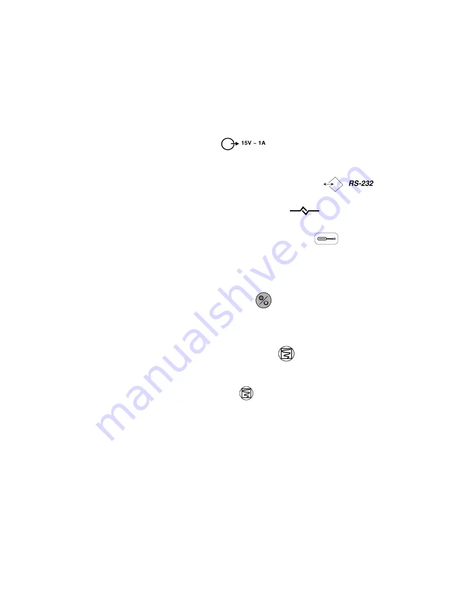
1. Connect the output of the appropriate power supply, PS-240V or PS-120V, to
the labeled connector
on the rear of the printer. When the
printer’s external power supply is connected, the printer front-panel charging
LED is lit.
2. Connect the serial cable between the labeled connectors
on the
rear panels of the monitor and the printer.
3. The printer front panel communication LED
is lit when the RS-232
communications link is completed.
4. Rotate the monitor wheel to highlight the setup icon
. Press the wheel
and ensure Communications Selection is
Printer
.
5. Connect a M4787A sensor extension cable to the monitor. Connect an oxygen
transducer to the sensor extension cable. Attach it to the subject as described in
the sensor directions for use.
6. Press the
ON/STANDBY
button
to turn the monitor on and verify that
the monitor is operating.
7. The monitor should stabilize on the subject’s physiological signal in about 15 to
30 seconds. Verify that the saturation and heart rate is reasonable for the subject.
8. Press the printer
CONTINUOUS
button
. Verify that the printout contains
vital signs across the top of the paper, and that a SpO
2
waveform, with grid
marks, occupies the center portion of the paper. To terminate the printout, press
the
CONTINUOUS
button
again.
9. Disconnect the sensor and shut off the monitor.
Содержание M3921A
Страница 12: ...xii Contents ...
Страница 16: ...Related Documents 4 Introduction ...
Страница 48: ...Safety Tests 36 Performance Verification ...
Страница 72: ...Troubleshooting Guide 60 Chapter 5 Troubleshooting ...
Страница 99: ...Disassembly Procedures A3 Chapter 6 Disassembly Guide 87 NiBP pump assembly Main PCB Main ribbon cable ...
Страница 100: ...Disassembly Procedures A3 88 Chapter 6 Disassembly Guide ...
Страница 102: ...Top Level Assembly 90 Chapter 7 Spare Parts Top Level Assembly Figure 1 A1 Top Level Assembly Drawing 1 of 2 ...
Страница 103: ...Top Level Assembly Chapter 7 Spare Parts 91 Figure 2 A1 Top Level Assembly Drawing 2 of 2 ...
Страница 105: ...Top Level Assembly Chapter 7 Spare Parts 93 Figure 3 A3 Top Level Assembly Drawing ...
Страница 107: ...Front Case Assembly Chapter 7 Spare Parts 95 Front Case Assembly Figure 4 A1 Front Case Assembly Drawing 1 of 3 ...
Страница 108: ...Front Case Assembly 96 Chapter 7 Spare Parts Figure 5 A1 Front Case Assembly Drawing 2 of 3 ...
Страница 110: ...Front Case Assembly 98 Chapter 7 Spare Parts Figure 7 A3 Front Case Assembly Drawing 1 of 2 ...
Страница 111: ...Front Case Assembly Chapter 7 Spare Parts 99 Figure 8 A3 Front Case Assembly Drawing 2 of 2 ...
Страница 114: ...Rear Case Assembly 102 Chapter 7 Spare Parts Figure 9 A3 Rear Case Assembly Drawing 1 of 3 ...
Страница 115: ...Rear Case Assembly Chapter 7 Spare Parts 103 Figure 10 A3 Rear Case Assembly Drawing 2 of 3 ...
Страница 116: ...Rear Case Assembly 104 Chapter 7 Spare Parts Figure 11 A3 Rear Case Assembly Drawing 3 of 3 ...
Страница 124: ...Repacking In A Different Carton 112 Chapter 8 Packing For Shipment ...
Страница 132: ...Theory of Operation and System Architecture 120 Chapter 10 Training Program Block Diagram A1 Figure 1 A1 Block Diagram ...
Страница 144: ...Preventative Maintenance 132 Chapter 10 Training Program ...
Страница 150: ......


