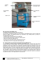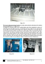
CONTROL
PANEL
TOTAL PROTECTION
OF WORKING AREA
LOAD BEARING
FRAME
LEFT OPENABLE
PANEL
BASE PLATE
DOOR OF ELECTRIC
CABINET
DOOR OF PNEUMATIC
PANEL
Dwg. A1.1
B)
Load bearing frame
(Dwg. A1.1)
It consists of a structure of steel plates and tubular.
The elements composing the frame are assembled by intermittent weld in order to obtain the
maximum rigidity. The following groups are connected to the holding frame by means of
commercial bolts and nuts:
- holding surface and automatic frame positioning
- group for lifting and forward movement of cutter’s packs
- motor and cutter pack support group
- locking device with upper knife for welding seal removal
- total safety guards for moving parts and working area
C)
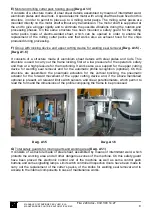
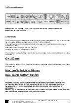
- Holding surface and automatic frame positioning group
(Dwg. A1.2)
It is composed of a sheet structure connected to the holding frame, on which have been fixed
brushes with short and hard bristles, turned upwards, which permit to support the frame to be
processed at the same height of the reference horizontal surfaces for working on the load
bearing frame and on which have been fixed the reference shoulders which permit to obtain the
proper frame position. In order to obtain this position, the operator has to put the frame by hand
onto the machine and push it into contact with the two shoulders. In this way, the mobile part of
the shoulders is able to activate the microswitches placed in the fixed part and to start the
working cycle. Automatically a mechanical device controlled by pneumatic cylinders is activated,
to position the frame in the right position to be processed.
MANUALE D’ISTRUZIONE PER L’USO E LA
MANUTENZIONE PULITRICE AUTOMATICA CM4S
7
File: 2240.doc - 03/11/03 14:27


