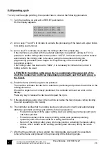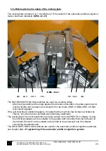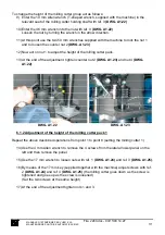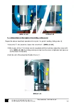
REMOVE
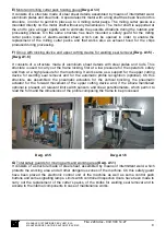
DWG. A1.12
At this moment, the operations to be done concern the connection of the various systems as
described in chapters 4.5 and 4.6.
Before setting the machine to work, especially if it is the first start-up or when it is installed in a
new working place, it is necessary to consider the following technical information and the
indications concerning the various connection types.
Mounting of profile holding arms (optional)
.
The mounting and adjustment of this device
(optional) is carried out in our workshop during the machine mounting phase, but it is partly
removed by the machine to facilitate the packaging and shipment operations. To mount this
device during the installation phase, proceed as follows:
- Put arm (1) and (2)
(DWG. A1.14)
into supports (3)
(DWG. A1.13)
fixed on the base plate of
the machine.
- Mount the bush (6)
(DWG. A1.14)
and the self-locking nut (7)
(DWG. A1.14),
using the 24 mm
key supplied. Do not lock the nut completely, but screw it enough to remove the clearance
between the arm and the support, in order to allow the rotation of the same arm.
- The height adjustment of the arm is carried out during the machine mounting phase. Anyway,
it is always better to proceed with a check in the following way:
- carry out a working cycle to block a frame on the working surface;
- check that the parts made of plastic material of the profile supporting arms (4)
(DWG. A1.14)
,
are on the same level of the lower face of the profiles;
- in case the parts made of plastic material result higher or lower, proceed with the height
regulation by loosing screws (5)
(DWG. A1.13)
only in part, with the 13 mm key supplied. These
screws fix the supports on the base and move the supports upwards and downwards (3)
(DWG.
A1.13)
;
- find the correct position and tighten the screws completely (5)
(DWG. A1.13)
. Carry out this
operation on both sides.
MANUALE D’ISTRUZIONE PER L’USO E LA
MANUTENZIONE PULITRICE AUTOMATICA CM4S
19
File: 2240.doc - 03/11/03 14:27

