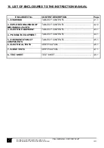
ELECTRICAL EQUIPMENT
HOW TO USE THE DOCUMENTATION
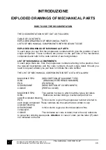
THE DOCUMENTATION IS SET OUT AS FOLLOWS:
CONTENTS
ELECTRIC DIAGRAMS
ELECTRIC COMPONENTS ASSEMBLY DRAWINGS
LIST OF ELECTRIC COMPONENTS
ELECTRIC DIAGRAMS
Each page provides the co-ordinates of a symbol through letters along the horizontal
axis and numbers along the vertical axis.
The reference ---> Drwg. A3.5-a1 indicates that the conductor is continued in
drawing A3.5 at co-ordinates a1 (top left).
The reference >--- Drwg. A3.4-q1 indicates that the conductor continues from
drawing A3.4 at co-ordinates q1 (top right).
The connectors used are illustrated in the diagrams together with the corresponding
connector number ( C 2 ) and position of the conductor inside ( 12 ).
C 2
12
LIST OF ELECTRIC COMPONENTS
THE LIST OF ELECTRIC COMPONENTS IS SET OUT AS FOLLOWS:
RIF. (REFERENCE)
TAV. (DRAWING)
DESCRIZIONE (MATERIAL DESCRIPTION)
NUM. (NUMBER OF PIECES)
TIPO (TYPE OR CODE - MATERIAL MANUFACTURER)
FORNITORE (MATERIAL SUPPLIER)
NS. CODICE (PERTICI CODE)
MANUALE D’ISTRUZIONE PER L’USO E LA
MANUTENZIONE PULITRICE AUTOMATICA CM4S
49
File: 2240.doc - 03/11/03 14:27


