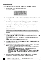
To change the height of the milling cutter group act as follows:
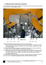
9) Enter the 10 mm Allen wrench (T-shaped wrench, supplied with the machine) in the
relevant seat of the milling cutter holding shaft with ref. 3
(DWG. A1.22)
10) Enter the 46 mm wrench into the nut with ref. 4
(DWG. A1.22)
Loosen the nut by turning the wrench in the arrow direction.
11) At this point use the two 50 mm wrenches supplied with the machine to lock the nut 1
and to loosen the counter nut 2
(DWG. A1.23)
12) Now act on nut 1 to adjust the height of the milling cutter pack.
13) At the end of the adjustment, tighten counter nut 2
(DWG. A1.23)
and nut 4
(DWG.
A1.22)
.
DWG. A1.22 DWG. A1.23
6.1.2 Adjustment of the height of the milling cutter pack 1
Repeat the above described operations from point 1 to point 8 (setting the milling cutter 1)
14) Use the 4 mm Allen wrench to remove the 4 screws from the lateral lower panel on the
left and then remove the panel.
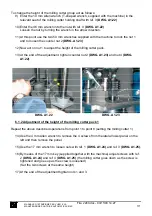
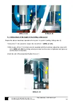
15) Use the 17 mm wrench to loosen nuts with ref. 1
(DWG. A1.24)
and ref. 3
(DWG. A1.25)
.
16) By means of the 17 mm key (supplied together with the machine) adjust screws with ref.
2
(DWG. A1.24)
and ref. 4
(DWG. A1.25)
(the milling cutter goes down as the screw is
tightened and goes up as the screw is loosened)
(Set the two screws at the same height)
17) At the end of the adjustment tighten nuts 1 and 3.
MANUALE D’ISTRUZIONE PER L’USO E LA
MANUTENZIONE PULITRICE AUTOMATICA CM4S
31
File: 2240.doc - 03/11/03 14:27


