


a good earth connection to the PAC, which can be accomplished by attaching the DIN rail to a suitable
Earth ground and also utilizing Pin-3 on the Controller DC power input connector. This connection must
be made with the shortest possible, heavy gage wire or braided cable. Low-resistance (<0.5 ohms)
continuity should be verified with an ohmmeter for proper grounding. In addition, all communication
cables should be shielded and grounded, preferably only on one end.
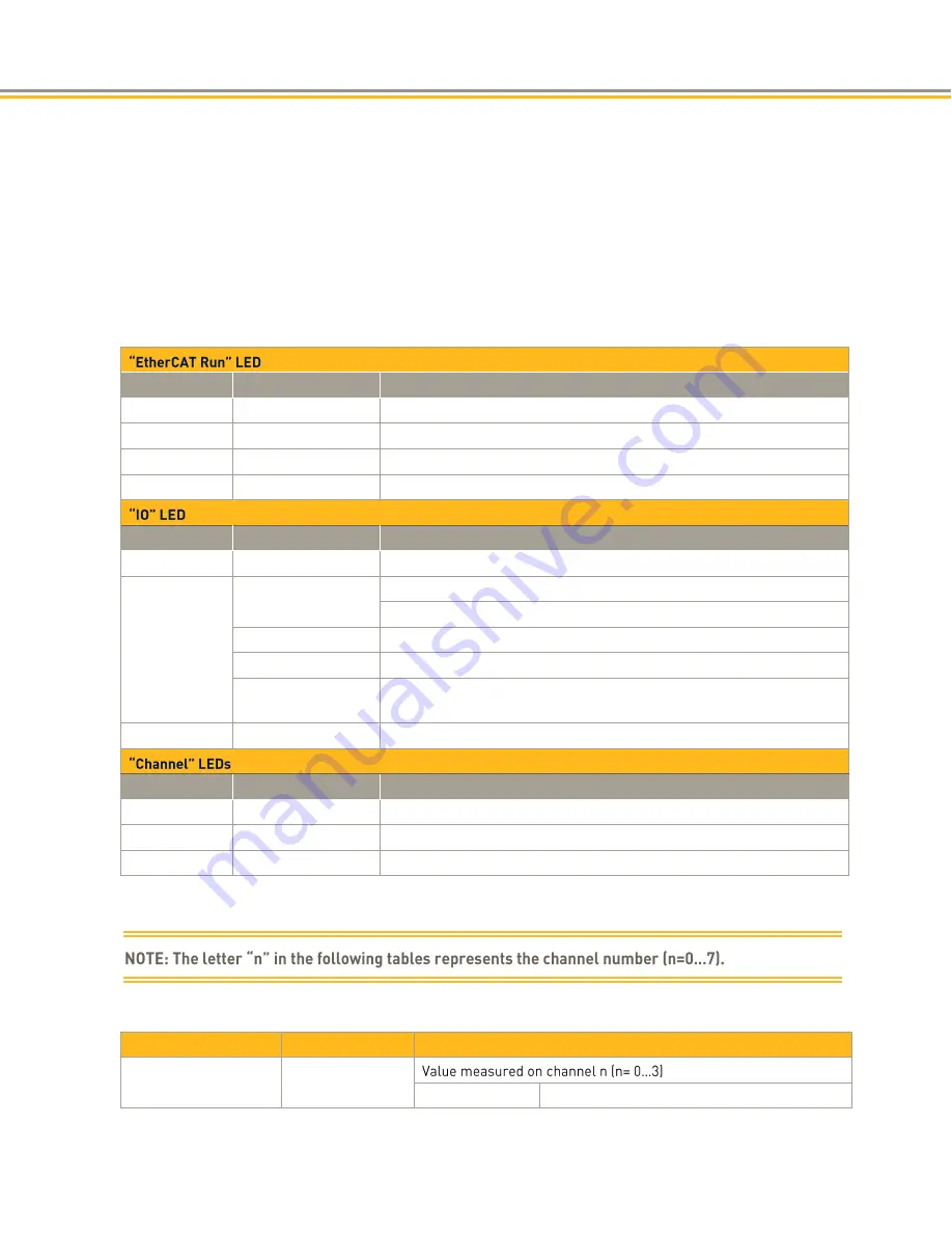
Status LEDs
The LED labeled "EtherCAT" indicates the state of the EtherCAT ASIC. The LED labeled "IO" indicates the
state of the Module inputs and outputs.
State
LED Flash Code
Explanation
Init
Red, on
Initializing, no data exchange
Pre-Op
Red/green, 1:1
Pre-operational, no data exchange
Safe-Op
Red/green, 5:1
Safe operation, inputs readable
Op
Green, on
Operational, unrestricted data exchange
State
LED Flash Code
Explanation
Ok
Green, on
No error
Error
Off
Malfunction of Module if E-Bus LED = On
Inoperative if E-bus LED = Off
Red, 4x
EtherCAT watchdog control
Red, 6x
Module-specific fault
Red, 7x
Configuration error (E-Bus pre-operational), number of process data
differs from that in the Module
Defective
Red, on
Module defective
State
LED Flash Code
Explanation
On
Green, on
Channel enabled
Off
Off
Channel disabled
Error
Red
Short circuit, Broken wire
Analog Inputs
Check the following variable for the digitized input values.
Variable
Data type
Explanation
Channel_n
INT
Default
in 1/10 °C
Содержание PAC
Страница 11: ...CHAPTER 1 Product Overview...
Страница 18: ......
Страница 19: ...CHAPTER 2 Installation...
Страница 33: ...CHAPTER 3 System Start up and Configuration...
Страница 69: ...CHAPTER 4 PACIO Modules...
Страница 143: ...2 After adding the device and code to the project you will configure the IO map as displayed...
Страница 155: ...PAC with 400XR series...
Страница 156: ...PACIO MODULES 156 Parker Automation Controller Installation Guide...
Страница 157: ...PAC with 400LXR...
Страница 158: ...PACIO MODULES 158 Parker Automation Controller Installation Guide PAC with SMH sensors...
Страница 159: ...CHAPTER 5 Communication Interfaces Optional...
Страница 176: ......
Страница 177: ...CHAPTER 6 Troubleshooting...
Страница 188: ...TROUBLESHOOTING 188 Parker Automation Controller Installation Guide...
Страница 189: ...APPENDIX A PAC System Specifications...
Страница 195: ...APPENDIX B Additional Information...