


Chapter 1. Installation
2 1
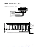
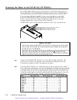
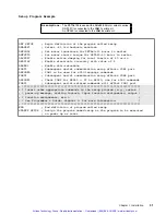
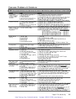
Connections
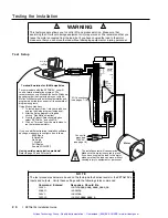
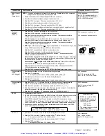
Test Procedure
Response Format
(left to right)
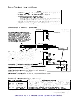
End-of-travel
and
Home Limits
NOTE
: If you are not using end-of-travel limits, issue the Disable Limits (
LH¯
) command
and ignore the first two bits in each response field.
1. Enable the hardware end-of-travel limits with the
LH3
command.
2. Close the end-of-travel switches and open the home switch.
3. Enter the
TLIM
command. The response should be
*TLIM11¯
.
4. Open the end-of-travel switches and close the home switch.
5. Enter the
TLIM
command. The response should be
*TLIM¯¯1
.
6. Close the end-of-travel switches and open the home switch (return to original config.).
7. Enter the
TLIM
command. The response should be
*TLIM11¯
.
TLIM
response:
bit 1= POS (positive travel) limit
bit 2= NEG (negative travel) limit
bit 3 = HOM (home) limit
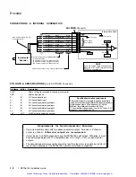
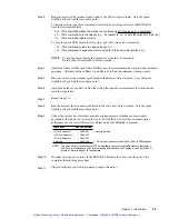
Motor and
Encoder
(motion)
1. Enter the
ENC¯
command to enable the motor step mode.
Enter the
PSET¯
command to set the motor position to zero.
Enter the
TPM
command to determine the motor position.
The response should be
*TPM+¯
(motor is at position zero).
Enter the
D25¯¯¯
command, followed by the
GO
command. The motor will move one
revolution (25000 steps) in the clockwise direction (viewed from the flange end).
Enter the
TPM
command to determine the motor position.
The response should be
*TPM+25¯¯¯
(motor is at position 25000).
2.
NOTE:
Ignore this step if you are
not
using encoder feedback. This test assumes you are
using a 1000-line encoder yielding a 4000 count/rev resolution.
Enter the
ENC1
command to enable the encoder step mode.
Enter the
PSET¯
command to set the encoder position to zero.
Enter the
TPE
command to determine the encoder position. The response should be
*TPE+¯
(encoder is at position zero).
If the encoder is coupled to the motor shaft:
Enter the
D4¯¯¯
command, followed by
the
GO
command. The encoder (and motor) will move one revolution (4000 counts) in the
clockwise direction (viewed from the flange end).
If the encoder is not coupled to the motor shaft:
Manually rotate the encoder shaft
one revolution in the clockwise direction (viewed from the flange end).
Enter the
TPE
command to determine the encoder position.
The response should be
*TPE+4¯¯¯
(encoder is at position 4000).
Enter the
ENC¯
command to return the ZETA6104 to the default motor step mode.
TPM
response = motor counts
TPE
response = encoder counts
Direction of rotation:
Counter-clockwise
(negative counts)
Clockwise
(positive counts)
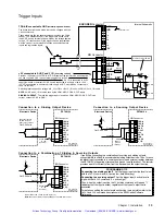
Programmable
Inputs
(incl. triggers)
1. Open the input switches or turn off the device driving the inputs.
2. Enter the
TIN
command.
The response should be
*TIN¯¯¯¯_¯¯¯¯_¯¯¯¯_¯¯¯¯_¯¯
.
3. Close the input switches or turn on the device driving the inputs.
4. Enter the
TIN
command.
The response should be
*TIN1111_1111_1111_1111_11
.
TIN
response:
bits 1-16 = prog. inputs 1-16
bits 17 & 18 = TRG-A & TRG-B
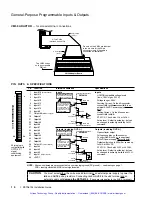
Programmable
Outputs
1. Enter the
OUTALL1,9,1
command to turn on (sink current on) all programmable
outputs. Verify that the device(s) connected to the outputs activated properly.
2. Enter the
TOUT
command.
The response should be
*TOUT1111_1111_1
.
3. Enter the
OUTALL1,9,¯
command to turn off all programmable outputs. Verify that the
device(s) connected to the outputs de-activated properly.
4. Enter the
TOUT
command.
The response should be
*TOUT¯¯¯¯_¯¯¯¯_¯
.
TOUT
response:
bits 1-8 = prog. outputs 1-8
bit 9 = OUT-A
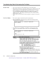
RP240
1. Cycle power to the ZETA6104.
2. If the RP240 is connected properly, the RP240Õs status LED should be green and one of the
lines on the computer or terminal display should read
*RP24¯ CONNECTED
.
If the RP240Õs status LED is off, check to make sure the +5V connection is secure.
If the RP240Õs status LED is green, but the message on the terminal reads
*NO REMOTE
PANEL
, the RP240 Rx and Tx lines are probably switched. Remove power and correct.
3. Assuming you have not written a program to manipulate the RP240 display, the RP240
screen should display the following:
COMPUMOTOR 6104 INDEXER/DRIVE
RUN JOG STATUS DRIVE DISPLAY ETC
ASSUMPTIONS
¥ RP240 connected to
COM 2
¥
COM 2
(PORT2) configured
for RP240. To verify, type
these commands:
PORT2
<cr>
DRPCHK
<cr>
The system response should
report Ò
*DRPCHK3
Ó.
Pulse Cut
1. Open the P-CUT switch or turn off the device driving the P-CUT input.
2. Enter the
TINO
command (note the condition of the 6
th
bit from the left).
The response should be
*TINO¯¯¯¯_¯¯¯¯
.
3. Close the P-CUT switch or turn on the device driving the P-CUT input.
4. Enter the
TINO
command.
The response should be
*TINO¯¯¯¯_¯1¯¯
.
TINO
response:
bit 6 = pulse cut input
bits 1-5, 7 & 8 are not used
Artisan Technology Group - Quality Instrumentation ... Guaranteed | (888) 88-SOURCE | www.artisantg.com
Содержание Compumotor ZETA6104
Страница 45: ...Artisan Technology Group Quality Instrumentation Guaranteed 888 88 SOURCE www artisantg com...
Страница 49: ...Artisan Technology Group Quality Instrumentation Guaranteed 888 88 SOURCE www artisantg com...
Страница 53: ...Artisan Technology Group Quality Instrumentation Guaranteed 888 88 SOURCE www artisantg com...
Страница 63: ...Artisan Technology Group Quality Instrumentation Guaranteed 888 88 SOURCE www artisantg com...


