


Chapter 1. Installation
9
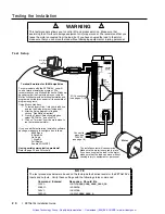
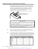
Motor (ZETA and OS/RS motors only)
INTERLOCK
A
CENTERTAP
A+
AÐ
EARTH
B+
BÐ
B
CENTERTAP
INTERLOCK
MOTOR
Motor Connector
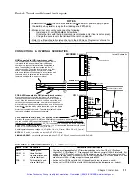
WARNING
: Remove AC power
before connecting or disconnecting
the motor. Lethal voltages are
present on the screw terminals
ZETA, OS and RS Motors
Specifications Ð see page 3.
Speed/Torque curves Ð see page 10.
Considerations for series & parallel wiring Ð see page 10.
Current settings Ð see page 4. Dimensions Ð see page 24.
Cable extension Ð see table below.
ZETA & RSxxx-xxC10 motors include a rubber boot for safety.
Non-Compumotor Motors
If you intend to use a non-Compumotor motor, refer to
Appendix B for connection instructions and current selection.
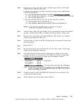
Do not lengthen or
remove this jumper.
NOTE:
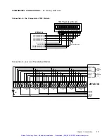
ZETA motors are shipped from the factory wired to the connector in series.
Series Connection
Red
Blue
Yellow
Black
White
Brown
Orange
Green
See page 10 for guidelines about using a motor in parallel.
Parallel Connection
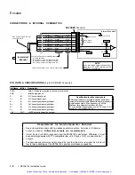
Shield is connected to the motor case and
is internally connected to the ground pin
on the ZETA6104Õs AC power connector.
PM
Phase A
Windings
Phase B
Windings
Motor
Yellow
Blue
Red
Black
Shield
White
Green
Orange
Brown
PM
Phase A
Windings
Phase B
Windings
Motor
Shield
INTERLOCK
A
CENTERTAP
A+
AÐ
EARTH
B+
BÐ
B
CENTERTAP
INTERLOCK
INTERLOCK
A
CENTERTAP
A+
AÐ
EARTH
B+
BÐ
B
CENTERTAP
INTERLOCK
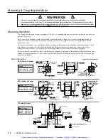
End Cover Removed
Schematic View
PM
Phase A
Windings
Phase B
Windings
1
6
5
3
2
8
7
4
Wire #1
Wire #3
Gnd (Grn/Ylw)
Wire #2
Wire #4
The green/yellow (Gnd) wire is for safety
purposes. The shield connection to the motor
case is for EMI purposes (the C10 cable kit
provides hardware for the shield connection).
C10 cable assembly instructions are provided
in the C10 cable kit.
INTERLOCK
A
CENTERTAP
A+
AÐ
EARTH
B+
BÐ
B
CENTERTAP
INTERLOCK
1
2
7
8
4
6
5
3
Gnd
1
3
2
4
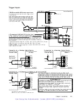
EARTH
A+ A- B+ B-
Motor Terminal Number/Wire Number:
ZETA6104 Motor Connector Terminal:
PM
Phase A
Windings
Phase B
Windings
1
6
5
3
2
8
7
4
Wire #1
Wire #3
Gnd (Grn/Ylw)
Wire #2
Wire #4
INTERLOCK
A
CENTERTAP
A+
AÐ
EARTH
B+
BÐ
B
CENTERTAP
INTERLOCK
1
2
7
8
4
6
5
3
Gnd
1
3
2
4
EARTH
A+ A- B+ B-
Motor Terminal Number/Wire Number:
ZETA6104 Motor Connector Terminal:
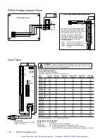
Series Connection
Parallel Connection
ZETA, OS and RS Motor Connections
RSxxx-xxNPS and RSxxx-xxC10 Motor Connections
The green/yellow (Gnd) wire is for safety
purposes. The shield connection to the motor
case is for EMI purposes (the C10 cable kit
provides hardware for the shield connection).
C10 cable assembly instructions are provided
in the C10 cable kit.
Auto Current Standy Mode
: Reduces motor current by 50% when step pulses from the ZETA6104 have stopped for one second
(
CAUTION
: torque is also reduced). Full current is restored upon the first step pulse. Enable with
the
DAUTOS1
command; disable with the
DAUTOS¯
command (default is disabled). For more
information, refer to the
DAUTOS
command in the 6000 Series Software Reference.
Extending ZETA Motor Cables
Standard length is 10 ft (3 m);
maximum extended length is 200 ft (61 m).
CAUTION
: Cables longer than 50 feet (15 m) may degrade
performance.
Max. Current
< 100 ft (30 m)
100-200 ft (30-60 m)
Motor Type
(amps)
AWG
mm
2
AWG
mm
2
ZETA57-51(S)
1.26
22
0.34
20
0.50
ZETA57-51(P)
2.38
22
0.34
20
0.50
ZETA57-83(S)
1.51
22
0.34
20
0.50
ZETA57-83(P)
3.13
22
0.34
20
0.50
ZETA57-102(S)
1.76
22
0.34
20
0.50
ZETA57-102(P)
3.50
20
0.50
18
0.75
ZETA83-62(S)
2.26
22
0.34
20
0.50
ZETA83-62(P)
4.00
20
0.50
18
0.75
ZETA83-93(S)
2.88
22
0.34
20
0.50
ZETA83-93(P)
4.00
20
0.50
18
0.75
ZETA83-135(S)
3.50
20
0.50
18
0.75
ZETA83-135(P)
4.00
20
0.50
18
0.75
Extending OS and RS Motor Cables
-L10, -R10 & -C10 motors are shipped with 10 ft (3 m) cables;
-FLY motor is shipped with 1 ft (0.3 m) flying leads.
-NPS motor does not include cable/leads; 10-foot: use 18 AWG (0.75 mm
2
) wire.
LVD COMPLIANCE
: Maximum DC resistance between the ZETA6104Õs
ÒEARTHÓ terminal (Òprotective conductor terminalÓ) and motor body must not
exceed 0.1Ê
W
. (This criteria must be taken into consideration when sizing
cross-section (gage) for extended cable lengths.)
NON-LVD
: Maximum extended length is 200 ft (61 m), but cables longer than 50
feet (15 m) may degrade performance. See table below for guidelines:
Max. Current
< 100 ft (30 m)
100-200 ft (30-60 m)
Motor Type
(amps)
AWG
mm
2
AWG
mm
2
OS2HB(S)
1.51
22
0.34
20
0.50
OS2HB(P)
3.01
22
0.34
20
0.50
OS21B(S)
1.88
22
0.34
20
0.50
OS21B(P)
3.75
20
0.50
18
0.75
OS22B(S)
2.14
22
0.34
20
0.50
OS22B(P)
4.00
20
0.50
18
0.75
RS31B(S)
2.26
22
0.34
20
0.50
RS31B(P)
4.00
20
0.50
18
0.75
ZETA83-93(S)
2.88
22
0.34
20
0.50
ZETA83-93(P)
4.00
20
0.50
18
0.75
ZETA83-135(S)
3.50
20
0.50
18
0.75
ZETA83-135(P)
4.00
20
0.50
18
0.75
(
S)
= Series Configuration (P) = Parallel Configuration
NOTE
: Rated current in wire sizes shown may result in a maximum temperature rise of 18
°
F (10
°
C) above ambient.
Artisan Technology Group - Quality Instrumentation ... Guaranteed | (888) 88-SOURCE | www.artisantg.com
Содержание Compumotor ZETA6104
Страница 45: ...Artisan Technology Group Quality Instrumentation Guaranteed 888 88 SOURCE www artisantg com...
Страница 49: ...Artisan Technology Group Quality Instrumentation Guaranteed 888 88 SOURCE www artisantg com...
Страница 53: ...Artisan Technology Group Quality Instrumentation Guaranteed 888 88 SOURCE www artisantg com...
Страница 63: ...Artisan Technology Group Quality Instrumentation Guaranteed 888 88 SOURCE www artisantg com...


