background image

93

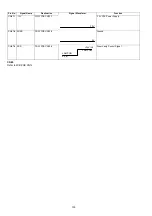
CN52

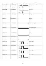
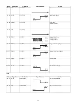
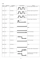
CN51-4 GND

LSU P101-4

Ground

CN51-5 nLDON

LSU P101-5

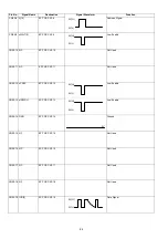
Laser Control Signal

CN51-6 nVIDEO

LSU P101-6

Video Data
L=Black, H=White

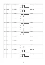
CN51-7 GND

LSU P101-7

Ground

CN51-8 nPMCK

LSU CN1-1

Polygon Motor Clock
3.3 KHz (16 dot)
5.1 KHz (600 dpi)

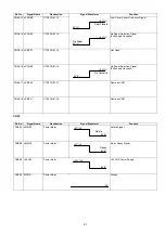
CN51-9 nPMRY

LSU CN1-2

Polygon Motor Ready Signal

CN51-10 nPMON

LSU CN1-3

Polygon Motor Control Signal

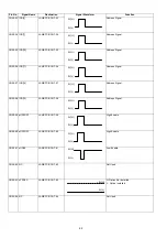
CN51-11 MGND

LSU CN1-4

Frame Ground

CN51-12 +24VM

LSU CN1-5

+24 VDC Power Supply

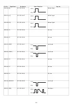
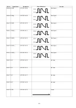
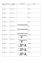
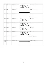
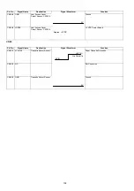
Pin No.

Signal Name

Destination

Signal Waveform

Function

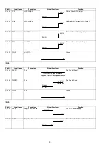
CN52-1 +24VM

HVPS CN39-1

+24 VDC Power Supply

CN52-2 nCR0

HVPS CN39-2

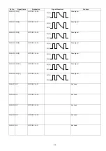
Charge Control AC Output

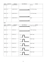
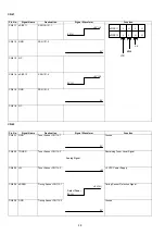
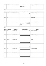
Pin No.

Signal Name

Destination

Signal Waveform

Function

0V

0V (L)

+5V (H)

OFF

ON

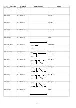
0V

+5V(H)

0V(L)

Ready

0V (L)

+5V (H)

Not Ready

0V (L)

+5V (H)

OFF

ON

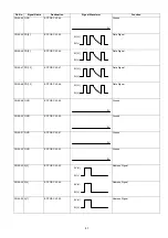
0V (L)

+24V (H)

0V (L)

+24V (H)

+24V (H)

0V (L)

Содержание Panafax DX-2000

Страница 1: ...Order Number MGCS001207C0 Facsimile DX 2000 2000 Matsushita Graphic Communication Systems Inc All rights reserved Unauthorized copying and distribution is a violation of law ...

Страница 2: ......

Страница 3: ... 9 Fuser Unit 431 Fuser Lamp 408 Thermistor Assembly 405 Paper Exit Sensor 610 39 2 10 Fuser Roller 414 Pressure Roller 409 Eject Roller 422 41 2 11 Fan Duct 520 Printer Motor 650 Motor Bracket 641 43 2 12 Laser Unit 429 Feed Roller 618 Paper Feed Roller 746 Clutch Gear Assembly 660 Paper Feed Solenoid 744 Fan Unit 622 45 2 13 ILS PC Board 621 No Paper Actuator 609 Catch Magnet 730 47 2 14 High Vo...

Страница 4: ...elephone Line Cable and Power Cord 306 8 7 Customizing Your Machine 307 Options and Supplies 313 9 1 Options and Supplies 313 9 2 Installing the Memory Card Flash Memory Card and or D RAM Card 315 9 3 Installing Optional Feeder Unit UE 409057 316 9 4 Installing Optional Feeder Unit UE 409056 318 9 5 Installing Page Description Language Printer Emulation Kit UE 403169 320 General Network Informatio...

Страница 5: ... a master firmware card backup and restore of firmware and machine parameters 4 Panasonic Super Smoothing The machine incorporates a new sophisticated image processing technology to enhance print quality of ordinary received fax images by smoothing the curved edges of the character 5 B4 size Scanning B4 size is the maximum document width that can be scanned and transmitted Note 11 inches is the ma...

Страница 6: ...l A communication journal is a result report of a communication which can be printed automatically after communication is completed Printout conditions can be selected for each communication to 1 not print 2 always print or 3 print when communication has failed 20 Multi purpose LCD Display The 20 x 2 Alphanumeric LCD display shows the operation mode date and time remote ID number and pages transmi...

Страница 7: ...ded regardless of the selection 28 Network Printer Internet Communication Feature The unit can be used as a network printer Documents created by personal computer applications can be sent from a PC connected to the LAN and printed at the Internet FAX To use the network printer function it is necessary to download the software from the Panasonic home page and install it on the PC 29 Fax Forward G3 ...

Страница 8: ...g the Internet Parameters One Touch Abbreviated Dialing Numbers and Program keys right from your PC by sending a text email message to the DX 2000 35 Internet Fax Return Receipt After a Panasonic Internet Fax is received a Internet Fax Return Receipt is returned to the sender with a portion of the received document attached in graphic form No Internet Fax Return Receipt is returned for email recei...

Страница 9: ...ified Read PSTN only MMR Modified Modified Read PSTN LAN 400 dpi scanning only JBIG Joint Bi level Experts Group PSTN only Standard 203 dpi x 98 lpi 8 pels mm x 3 85 lines mm Fine 203 dpi x 196 lpi 8 pels mm x 7 70 lines mm 400 dpi 203 dpi x 391 lpi 8 pels mm x 15 4 lines mm 406 dpi x 391 lpi 16 pels mm x 15 4 lines mm Standard 203 dpi x 98 lpi 8 pels mm x 3 85 lines mm Fine 203 dpi x 196 lpi 8 pe...

Страница 10: ...270 stations Registration Memory Capacity in One Touch and Abbreviated Dialing Number of Stations Up to 200 stations Telephone number of each station PSTN Up to 36 digits Including pauses and spaces Email Address of each station LAN Up to 60 characters Station name for each station Up to 15 characters Redialing Automatic Manual Up to 15 times with 0 to 15 minute intervals PSTN only By pressing the...

Страница 11: ...ette 500 sheets 75g m2 4 Printing Resolution 406 x 391 dpi Fax or Copy 600 x 600 dpi Printer Note Page Memory D RAM card is required for 600 dpi printing Width Minimum 148 mm Maximum 280 mm Length Minimum 128 mm Maximum 356 mm Paper thickness Single page 0 06 to 0 15 mm Multi page 0 06 to 0 12 mm Capacity 20 documents Legal Size 20 lb 50 documents Letter A4 Size 20 lb Horizontal Sheet Feeding with...

Страница 12: ...e stored upright 3 Transportation Environment Max 480 hours Carton Box Condition Within 70 seconds after turning the power on Room Temperature 20 to 35 C Power Voltage Minimum 115 V Maximum Approx 470 W Reception Approx 460 W Copy Approx 470 W Transmission Approx 23 W Standby Energy Saver Mode On Approx 14 W H Standby Energy Saver Mode Off Approx 82 W H Room temperature 25 C Temperature 10 to 35 C...

Страница 13: ...13 1 8 Construction 1 8 1 External View Dimensions W x D x H 437 x 493 x 307 mm Weight excluding paper Approximately 17 Kg 417 mm 632 mm 677 5 mm 437 mm 307 mm 394 mm 513 mm 538 mm 493 mm ...

Страница 14: ... 20 26 32 P6 03 09 15 21 27 P1 P7 04 10 16 22 28 P2 P8 05 11 17 23 29 P3 06 12 18 24 30 P4 g m s y c i o u d j p v e k q w f l r x VOLUME DIRECTORY SEARCH INTERNET MEMORY HALFTONE RESOLUTION CONTRAST LIGHTER FINE QUALITY DARKER ON LINE TONER ALARM 400 dpi FAST START STOP COPY 1 2 3 4 5 6 7 8 9 0 ABC DEF JKL MNO TUV WXY OPER GHI PRS TONE 205 mm 373 mm ...

Страница 15: ...3 x 196 8 pels x 7 7 lines mm 203 x 391 8 pels x 15 4 lines mm 406 x 391 16 pels x 15 4 lines mm Interpolated 203 x 98 8 pels x 3 85 lines mm 203 x 196 8 pels x 7 7 lines mm 406 x 391 16 pels x 15 4 lines mm 203 x 98 8 pels x 3 85 lines mm 203 x 196 8 pels x 7 7 lines mm 203 x 391 8 pels x 15 4 lines mm 203 x 98 8 pels x 3 85 lines mm 203 x 196 8 pels x 7 7 lines mm 406 x 391 16 pels x 15 4 lines ...

Страница 16: ... 12 2 440 x 492 x 310 mm 16 9 x 16 4 x 11 0 430 x 415 x 280 mm Weight 37 4 lbs 17 kg 33 lbs 15 kg Options Printer Interface Yes GDI PDL No Encryption Interface No Optional Recording Paper Cassette see Note Yes 250 500 or 250 500 sheets Yes 250 sheets Telephone Handset Yes Items DX 2000 DX 1000 PSTN LAN PSTN LAN Main Unit A4 LTR LGL 500 sheets Main Unit A4 LTR LGL 500 sheets A4 LTR LGL 500 sheets A...

Страница 17: ...ons No Yes 250 stations No Simultaneous Multi Station XMT No Yes 270 stns No Yes 200 stns Email G3 Mixed Broadcast Yes No Deferred Transmission No Deferred Multi Station XMT No Priority Direct Transmission Yes ADF TX Reserve No Yes ADF TX Reserve No Batch Transmission No Cover Sheet No File Transmission No Edit File Mode Yes No Reception Features Substitute Reception Yes Fixed Reduction Yes Auto R...

Страница 18: ...ctory Search List Yes Fax Parameter List Yes Internet Parameter List Yes File List Yes Character Code List No Directory Sheet Yes Callback Message No Identification Logo TTI 25 characters Multiple Logo No Character ID 16 characters No 16 characters No Numeric ID TSI CSI CIG 20 digits No 20 digits No Special Communication Password XMT RCV No Selective Reception TSI check No Relay XMT Request No Rel...

Страница 19: ...te fax communication During this mode automatic Redialing is not available Internal Demo No 2 W Leased Line No AI Intelligent Redial Yes Up to 4 files Yes Up to 2 files Auto Multi copy No Auto Forwarding Yes Check Call Function Yes Items DX 2000 DX 1000 PSTN LAN PSTN LAN ...

Страница 20: ...t Sensor 610 2 9 Thermistor Assembly 405 2 9 Eject Roller 422 2 10 Pressure Roller 409 2 10 Fuser Roller 414 2 10 Fuser Lamp 408 2 9 Laser Unit 429 2 12 Feed Roller 618 2 12 Paper Feed Roller 746 2 12 Clutch Gear Assembly 660 2 12 Paper Feed Solenoid 744 2 12 Fan Unit 622 2 12 Speaker 133 2 3 Paper Guide Cover 110 2 4 Transmit Guide 117 2 4 High Voltage PSU 506 2 14 Transmitter Chassis 301 2 6 Tra...

Страница 21: ... Cassette 1018 1 Turn the Power Switch to the OFF O position 2 Disconnect the Power Cord 1208 3 Disconnect the Telephone Line Cable 1207 and LAN Cable 4 Open the Control Panel Unit 5 Remove the Document Return Tray 138 and 139 6 Remove the Recording Paper Tray 1206 7 Remove the Paper Cassette 1018 2 1 4 3 3 5 6 7 ...

Страница 22: ...en the Printer Cover 122 2 Remove the Toner Cartridge 3 Open the Control Panel Unit 4 Remove 1 Screw B1 5 Remove the Memory Card Cover 115 6 Remove 4 Screws B1 7 Remove the Sub Rear Cover 114 8 Remove 2 Screws 23 Caution When re installing these machine screws screws with washers ensure they are placed on the top of the enclosure 9 Remove 2 Screws B1 1 2 3 7 6 4 5 6 6 9 8 ...

Страница 23: ...rite Core is inserted into the LANB PC Board CN7 11 Disconnect Connector CN1 and CN2 on the LANB PC Board 12 Remove 2 Screws 23 13 Remove the LANC PC Board 1101 and disconnect Con nector CN200 on the LANC PC Board 14 Remove 4 Screw 23 15 Remove the LANB PC Board 1102 16 Release the two PCB Spacers 146 17 Remove the FRM PC Board 1104 10 11 12 13 14 15 16 17 ...

Страница 24: ...he center and release the Latch Hook 23 Remove the Left Side Cover 107 24 Open the Control Panel Unit 25 2 Screws B1 26 Release the hook and remove the Front Cover 105 27 Disconnect Connector on the Speaker Harness 28 2 Screws B1 1 Screw 1Y 29 Remove the Speaker Assembly 133 18 19 21 23 10 10 22 25 26 29 27 28 28 ...

Страница 25: ...25 Cleaning Separation Rubber 229 1 Open the Control Panel Unit 2 Remove the Pre Feed Cover 223 3 Clean the Separation Rubber 229 with a soft cloth soaked with isopropyl alcohol 3 2 ...

Страница 26: ...ont Cover 105 and the Rear Cover 108 Refer to 2 3 2 2 Screws 19 3 Remove the Paper Guide Cover 110 4 5 Screws 19 5 Release two Latch Hooks 6 Remove the Transmit Guide 117 7 Remove the SNS Assembly Harness from the clamp 8 Disconnect Connector CN7 on the FCB PC Board 2 3 4 4 5 6 7 8 ...

Страница 27: ...27 9 1 Screw 19 10 Release two Latch Hooks 11 Remove the SNS Assembly 121 9 10 11 ...

Страница 28: ...he Rear Cover 108 Refer to 2 3 2 4 Screws 19 3 Pull out the Low Voltage Power Supply Assembly 4 Disconnect 4 Connectors on the Low Voltage Power Supply Assembly 5 Remove the Mylar Shield 508 6 3 Screws 19 7 Remove the Low Voltage Power Supply Unit 502 8 Disconnect all Connectors on the FCB PC Board 9 6 Screws C8 10 Remove the FCB PC Board 522 2 3 5 4 4 7 6 9 x6 10 8 ...

Страница 29: ...512 14 Disconnect Connector CN25 on the LCU PC Board 15 2 Screws C8 16 Remove the LCU PC Board 519 17 3 Screws 19 18 Remove the FCB Bracket 523 19 Disconnect all Connectors on the LPC PC Board 20 3 Screws C8 21 Remove the LPC PC Board 555 12 11 13 14 15 x2 16 17 17 18 21 20 19 ...

Страница 30: ...ss from the clamp 25 Remove the Control Panel Unit 26 Remove the Battery Holder 1114 Assembly 27 Release 4 Latch Hooks 28 Remove the Control Panel Chassis 216 29 Disconnect Connector CN41 on the PNL PC Board 30 15 Screws 7B 31 Release two Latch Hooks 32 Remove the PNL PC Board 214 25 24 23 22 27 28 26 29 30 x15 32 31 ...

Страница 31: ...on the back of the LCD Holder 38 Remove the LCD Holder 232 Cleaning ADF Roller 323 Pre Feed Roller 325 Feed Roller 328 Eject Roller 330 and the Scanner Glass 341 1 Open the Control Panel Unit 2 Clean the ADF Roller 323 Pre Feed Roller 325 Feed Roller 328 Eject Roller 330 and the Scanner Glass 341 with a soft cloth soaked with isopropyl alcohol 33 34 36 35 37 38 ...

Страница 32: ...ve the Front Bracket 2 136 5 4 Screws 19 6 Remove the Transmitter Chassis 301 Assembly 7 Disconnect Connector CN30 on the CCD PC Board 8 2 Screws 19 9 Remove the Scanner Assembly 340 Note When reinstalling the CCD Harness 1 Separate the CCD Harness 545 from the other harnesses 2 Place the other harnesses into the Harness Protector Film 556 Cleaning Mirror 1 337 Mirror 2 338 Clean the Mirror 1 337 ...

Страница 33: ...D Array Bracket 1 332 and LED Array Bracket 2 351 12 8 Screws 9H 13 Remove two LED Array Assemblies 333 Note UF 885 has only one LED Array Assembly 14 1 Screw 19 15 Remove the Stamp Holder 334 and Stamp Solenoid 335 10 x6 11 12 13 14 15 ...

Страница 34: ...crew 19 3 Remove the ADF Bracket 317 Assembly 4 Remove the ADF Roller 323 5 Remove the Pressure Spring Plate 324 6 Remove the Pre Feed Roller 325 Note Apply Molykote EM 502L Grease to the Pre Feed Roller 325 7 Remove the Ground Spring Plate A 316 8 Remove the document Eject Roller 330 Note Apply Molykote EM 502L Grease to the Eject Roller 330 9 2 Screws 19 10 Remove the Feed Roller 328 Note Apply ...

Страница 35: ... Glass 341 with a soft cloth soaked with isoproyl alcohol 13 Release the hook on the drive gear 14 Remove the B31B61 Drive Gear 314 15 Remove the Idle Shaft 331 and the B18 Drive Gear 348 Note Apply Molykote EM 502L Grease to the Idle Shaft 331 16 Remove 2 Latch Coil Springs 303 17 Remove 2 Latches 302 12 11 15 14 16 16 17 17 ...

Страница 36: ... Gear Assembly Note Apply Molykote EM 502L Grease to the Transmit Motor 346 Gear B35 Drive Gear Feed Roller 326 and B35 Drive Gear Eject Roller 326 20 Remove the B30 Gear 307 21 2 Screws 36 22 Remove the Transmit Motor 346 23 Remove the TMOT Harness 347 18 19 x6 20 21 23 22 ...

Страница 37: ...w 19 5 Remove the Toner Sensor Assembly 6 Disconnect Connector and remove the Harness from the Upper Transport Guide 7 Remove the Toner Sensor 639 8 4 Screws 19 Remove the resistor screw first 9 Remove the Ground Strap 653 10 Remove the Transport Unit 11 Disconnect Connector from the Timing Sensor 12 Remove the Harness from the Transport Unit 4 2 3 5 6 7 8 10 9 12 11 ...

Страница 38: ...19 14 Remove the Upper Transfer Guide 635 15 Release 2 Latch Hooks 16 Remove the Timing Sensor 610 17 2 Screws 19 18 Remove the BTR Guide 629 19 Remove the Bias Transfer Roller 630 13 14 16 15 19 17 17 18 Black White ...

Страница 39: ...Screw 23 9 Remove the Fuser Lamp Terminal C 404 10 Remove the Fuser Lamp 408 Caution When re installing the Fuser Lamp make sure that the Fuser Lamp is inserted into the Fuser Unit as illustrated on the left Do not touch the glass portion of the Fuser Lamp with bare hands Grease from the fingerprints will shorten its life cycle use isopropyl alcohol to clean fingerprints 11 1 Screw 1Q 12 Disconnec...

Страница 40: ...40 14 2 Screws 23 15 Remove the Fuser Cover 401 16 Remove the Paper Exit Sensor 610 17 Disconnect Connector 14 15 17 16 ...

Страница 41: ...Pressure Springs 412 3 2 C Rings 418 4 Remove the E24 Drive Gear 417 5 Remove 2 P17L6 8 Bushings 416 6 Remove the Fuser Roller 414 Caution Do not scratch the surface of the Fuser Roller when removing or re installing it 7 Remove the E22 Gear 425 8 1 Screw 4N 9 Remove the Lower Paper Guide 426 2 3 5 4 6 8 9 7 ...

Страница 42: ...e Pressure Roller 409 Caution Do not scratch the surface of the Pressure Roller when removing or re installing it 11 Remove the Black and the White Bushings 423 424 12 Remove the Eject Roller 422 10 12 11 White Black ...

Страница 43: ... Bracket 523 Refer to 2 5 2 2 Screws 19 3 Remove the Fan Duct 520 4 2 Screws 19 5 Remove the Fan Duct Bracket 526 6 Remove the Harnesses from the 4 clamps 7 Disconnect Connectors CN54 55 59 61 62 and 63 on the LPC PC Board 8 5 Screws 19 9 Remove the Motor Bracket 641 10 2 Screws 19 11 Remove the Printer Motor 650 2 3 11 10 10 11 10 10 11 10 10 ...

Страница 44: ...ing 649 14 7 Gears Caution When re installing the gear labeled 6 be sure to install the washer on the shaft first Note Apply KS 660 Conductive Grease to the Transfer Ground Spring 649 or to the end of the Feed Roller Shaft 618 Page 45 12 13 14 14 14 6 ...

Страница 45: ...110 Refer to 2 4 Control Panel Unit Refer to 2 5 and Motor Bracket and Gear Assembly Refer to 2 11 2 Disconnect Connectors 3 2 Screws 19 4 Remove the Laser Unit 429 5 Remove the E34 Drive Gear 620 Note When reassembling apply KS 660 Conductive Grease to the end of the Feed Roller Shaft 618 6 2 Screws 19 7 Remove the Feed Roller 618 8 2 Screws 19 9 Remove the Paper Feed Roller Assembly 3 4 2 5 6 7 ...

Страница 46: ... Rollers can be accessed from the bot tom of the machine after removing the Paper Cassette 14 Disconnect Connector CN55 on the LPC PC Board 15 1 Screw 19 16 Remove the Paper Feed Solenoid 744 17 Disconnect Connector CN54 on the LPC PC Board 18 2 Screws 1Y 19 Remove the Fan Unit 622 11 10 12 13 14 15 16 18 18 19 13 13 18 13 13 18 13 13 17 ...

Страница 47: ...Guide Cover 110 Refer to 2 4 Control Panel Unit Refer to 2 5 and Motor Bracket and Gear Assembly Refer to 2 11 2 Remove the ILS PC Board 621 3 Remove the No Paper Actuator 609 4 Remove the Paper Sensor 610 5 Pull out the Paper Sensor from the rear and disconnect the Connector 6 2 Screws 19 7 Remove the Catch Magnet 730 2 3 4 5 6 7 ...

Страница 48: ...e Front Cover 105 Refer to 2 3 2 1 Screw 19 3 Pull out the High Voltage Power Supply HVPS 506 4 Disconnect Connector CN39 on the High Voltage Power Supply HVPS 5 1 Screw 19 6 Release 2 Latch Hooks 7 Remove the High Voltage Terminal Cover 503 2 3 4 5 7 6 6 ...

Страница 49: ...49 2 15 Screw Identification Template ...

Страница 50: ...eriodic Maintenance Points No Tool No Tool 1 Soft Cloth 7 Pliers 2 Isopropyl Alcohol 8 Cotton Swab 3 Phillips Screwdriver 2 9 Brush 4 Stubby Phillips Screwdriver 2 10 KS 660 Conductive Grease 5 Blade tip Screwdriver 3 32 in 11 Molykote EM 502L Grease Dow Corning 6 Tweezer ...

Страница 51: ...ication Stamp 336 5 000 documents Page 32 Feed Roller 328 3 months Page 31 3 5 years 30 000 documents Page 34 Transmit Motor 346 5 years Page 34 Eject Roller 330 3 months Page 31 3 5 years 30 000 documents Page 34 Latch 302 12 months Toner Cartridge 10 000 pages See Note Feed Roller 618 12 months or 10 000 documents Alcohol Page 45 Clutch Gear Assembly 660 12 months or 10 000 documents Alcohol Pag...

Страница 52: ...tch to the ON I position 10 Use this Master Firmware Card to update the firmware on other machines 3 4 2 Updating the Firmware using the Master Firmware Card 1 Before starting print the Fax and Function Parameter Lists 2 Turn the Power Switch to the OFF O position 3 Install the appropriate Master Firmware Card into the machine 4 Turn the Power Switch to the ON I position 5 Perform the Service Mode...

Страница 53: ...d properly move the Pressure Adjusting Lever to the 1 L position Position Pressure of separator Situation 1 L Low When the documents misfeed 2 M Medium Normal Position Factory set position 3 H High When the documents multi feed UF 895 A L V02100 AB Country Code Firmware Version V0 2100 Language Code Firmware Type A Standard B Optional Model Number ...

Страница 54: ...t Pattern prints Check the print Quality Pattern Selection method Stop method Pattern 0 1 dot Horizontal line Switch ON for less than 2 seconds 400 dpi printing Switch ON again for less than 2 seconds Pattern 1 Blank page Switch ON for 2 seconds or more while Pattern 0 is printing 600 dpi printing Switch ON again for less than 2 seconds LPC PCB CN57 CN58 Test Pattern Print Switch CN61 SW401 ...

Страница 55: ...55 3 7 General Circuit Diagram 3 7 1 Fax Circuit 121 ADF 333 333 346 335 342 555 522 TEST POINTS LV PSU 502 519 133 214 LCD 215 ...

Страница 56: ...56 3 7 2 Printer Circuit 429 650 622 744 607 665 555 506 432 408 405 433 502 610 610 610 621 507 507 639 ...

Страница 57: ...57 3 7 3 Option Cassette Circuit 555 748 728 744 928 953 730 731 731 952 944 930 931 931 ...

Страница 58: ...58 3 7 4 LAN Control Circuit 522 CN50 1102 1104 1101 N C N C RD N C N C RD TD TD ...

Страница 59: ...59 3 7 5 Page Description Language Printer Interface Kit ...

Страница 60: ... Memory Card Data Signal CN1 5 IOD 6 Flash Memory Card Data Signal CN1 6 IOD 7 Flash Memory Card Data Signal CN4 DRAM Card CN5 CN9 CN11 13 1 CN2 2 1 CN3 15 1 CN13 12 1 CN12 13 1 1 4 CN8 1 3 CN7 1 7 CN10 6 1 9 1 CN1 Flash Memory Card 45 1 1 IC140 Image Processing Controller IC20 Main System Controller CN50 CN55 68 1 2 33 34 35 36 67 68 52 51 100 99 2 1 50 49 0V 5V H 0V L 5V H 0V L 5V H 0V L 5V H 0V...

Страница 61: ...mory Card Address Signal CN1 13 A 14 Flash Memory Card Address Signal CN1 14 A 15 Flash Memory Card Address Signal CN1 15 nWRL Flash Memory Card Low Enable CN1 16 pMIRQFR1 Flash Memory Card High Enable CN1 17 5V Flash Memory Card 5 VDC Power Supply CN1 18 12V Flash Memory Card 12 VDC Power Supply Pin No Signal Name Destination Signal Waveform Function 5V 3V H 0V L 3V H 0V L 3V H 0V L 3V H 0V L 3V ...

Страница 62: ...d Address Signal CN1 25 A 5 Flash Memory Card Address Signal CN1 26 A 4 Flash Memory Card Address Signal CN1 27 A 3 Flash Memory Card Address Signal CN1 28 A 2 Flash Memory Card Address Signal CN1 29 A 1 Flash Memory Card Address Signal CN1 30 IOD 0 Flash Memory Card Data Signal Pin No Signal Name Destination Signal Waveform Function 3V H 0V L 3V H 0V L 3V H 0V L 3V H 0V L 3V H 0V L 3V H 0V L 3V H...

Страница 63: ...stalled L Card Installed CN1 37 IOD 11 Flash Memory Card Data Signal CN1 38 IOD 12 Flash Memory Card Data Signal CN1 39 IOD 13 Flash Memory Card Data Signal CN1 40 IOD 14 Flash Memory Card Data Signal CN1 41 IOD 15 Flash Memory Card Data Signal CN1 42 nCS23 Flash Memory Card Low Enable Pin No Signal Name Destination Signal Waveform Function 5V H 0V L 5V H 0V L 3V H 0V L 0V 0V 0V L 5V H 5V H 0V L 5...

Страница 64: ... Flash Memory Card Address Signal CN1 49 A 21 Flash Memory Card Address Signal CN1 50 nCS2 Flash Memory Card Address Signal CN1 51 5V Flash Memory Card 5 VDC Power Supply CN1 52 12V Flash Memory Card 12 VDC Power Supply CN1 53 GND A22 Flash Memory Card Ground CN1 54 CN1 56 NC Not Used Pin No Signal Name Destination Signal Waveform Function 3V H 0V L 3V H 0V L 3V H 0V L 3V H 0V L 5V H 0V L 5V 12V 0...

Страница 65: ... Card ID CN1 63 nOPM13 Flash Memory Card Flash Memory Card ID CN1 64 nIOD 8 Flash Memory Card Data Signal CN1 65 IOD 9 Flash Memory Card Data Signal CN1 66 IOD 10 Flash Memory Card Data Signal CN1 67 nOPM12 Flash Memory Card Flash Memory Card ID CN1 68 GND Flash Memory Card Ground Pin No Signal Name Destination Signal Waveform Function 3V H 0V L 0V 5V or 0V 5V or 5V H 0V L 5V H 0V L 5V H 0V L 0V 5...

Страница 66: ... Ground CN3 4 24V LCU PCB CN25 4 24 VDC Power Supply CN3 5 pCMLD LCU PCB CN25 5 Line Switching Relay Drive CN3 6 pPLSD LCU PCB CN25 6 Pulse Dial Relay Drive CN3 7 nTSTSW RMCK LCU PCB CN25 7 Not Used CN3 8 nHSDT RMCS LCU PCB CN25 8 Handset Off Hook Detection Signal CN3 9 nHKOF RMDT LCU PCB CN25 9 External Phone Off Hook Detection Signal Phone Line must be connected 1V 1V Max Max 0V 5V 0V 24V 5V H 0...

Страница 67: ... CN25 14 Not Used CN3 15 pEAKD LCU PCB CN25 15 Not Used Pin No Signal Name Destination Signal Waveform Function CN4 1 GND DRAM Card Ground CN4 2 GND DRAM Card Ground CN4 3 5V DRAM Card 5 VDC Power Supply CN4 4 CID0 DRAM Card H Card Not Installed L Card Installed CN4 5 5VIMD 0 DRAM Card Data Signal Pin No Signal Name Destination Signal Waveform Function H Standby Mode L Ring in 0V 0V 0V 5V 0V L 5V ...

Страница 68: ...ata Signal CN4 12 5VIMD 7 DRAM Card Data Signal CN4 13 5VIMD 8 DRAM Card Data Signal CN4 14 5VIMD 9 DRAM Card Data Signal CN4 15 5VIMD 10 DRAM Card Data Signal CN4 16 5VIMD 11 DRAM Card Data Signal CN4 17 5VIMD 12 DRAM Card Data Signal Pin No Signal Name Destination Signal Waveform Function 5V H 0V L 5V H 0V L 5V H 0V L 5V H 0V L 5V H 0V L 5V H 0V L 5V H 0V L 5V H 0V L 5V H 0V L 5V H 0V L 5V H 0V ...

Страница 69: ...Address Signal CN4 24 IMA 3 DRAM Card Address Signal CN4 25 IMA 4 DRAM Card Address Signal CN4 26 IMA 5 DRAM Card Address Signal CN4 27 IMA 6 DRAM Card Address Signal CN4 28 IMA 7 DRAM Card Address Signal CN4 29 IMA 8 DRAM Card Address Signal Pin No Signal Name Destination Signal Waveform Function 5V H 0V L 5V H 0V L 5V H 0V L 3V H 0V L 3V H 0V L 3V H 0V L 3V H 0V L 3V H 0V L 3V H 0V L 3V H 0V L 3...

Страница 70: ... Enable CN4 36 nICAS DRAM Card Low Enable CN4 37 nIRAS 5 DRAM Card Low Enable CN4 38 nIRAS 4 DRAM Card Low Enable CN4 39 nIRAS 3 DRAM Card Low Enable CN4 40 nIRAS 2 DRAM Card Low Enable CN4 41 nIMWR DRAM Card Low Enable Pin No Signal Name Destination Signal Waveform Function 3V H 0V L 0V L 5V H or 0V L 5V H or 0V L 5V H or 3V H 0V L 3V H 0V L 3V H 0V L 3V H 0V L 3V H 0V L 3V H 0V L 3V H 0V L ...

Страница 71: ... PCB CN30 1 Sampling Clock CN5 2 FSG CCD PCB CN30 2 Data Transfer Enable Signal CN5 3 AGND CCD PCB CN30 3 Ground CN5 4 12V CCD PCB CN30 4 12 VDC Power Supply CN5 5 nVIDEO CCD PCB CN30 5 Video Signal CN5 6 GND CCD PCB CN30 6 Ground CN5 7 FCK2 CCD PCB CN30 7 Shift Register Clock 2 Pin No Signal Name Destination Signal Waveform Function 3V H 0V L 5V 0V 0V 5V 0V 320 ms 0 87 ms 0V 12V 3 5V 0V 0V 640 ns...

Страница 72: ... 4 nSDOOR SNS PCB CN31 4 Tx Door Detection CN7 5 nB4SN SNS PCB CN31 5 B4 Width Document Detection CN7 6 GND SNS PCB CN31 6 Ground CN7 7 12V SNS PCB CN31 7 12 VDC Power Supply Connector Unplugged 3 5 VDC Connector Plugged In Pin No Signal Name Destination Signal Waveform Function CN8 1 24V Stamp 24 VDC Power Supply Pin No Signal Name Destination Signal Waveform Function 640 ns 5V 0V 5V 0V 320 ms No...

Страница 73: ...VDC Connector Plugged In CN9 4 LEDD LED Array 1 2 LED Lamp 24 VDC Connector Unplugged 12 5 VDC Connector Plugged In Pin No Signal Name Destination Signal Waveform Function CN10 1 pTMA Transmit Motor Stepping Signal CN10 2 24V Transmit Motor 24 VDC Power Supply CN10 3 nTMA Transmit Motor Stepping Signal CN10 4 pTMB Transmit Motor Stepping Signal Pin No Signal Name Destination Signal Waveform Functi...

Страница 74: ...Supply CN11 3 5V PNL PCB CN40 3 5 VDC Power Supply CN11 4 GND PNL PCB CN40 4 Ground CN11 5 GND PNL PCB CN40 5 Ground CN11 6 pPNLCK PNL PCB CN40 6 Serial Data Transfer Clock CN11 7 PNLRXD PNL PCB CN40 7 Reception Data CN11 8 PNLTXD PNL PCB CN40 8 Transmission Data CN11 9 pPNLRST PNL PCB CN40 9 Panel Reset Signal Reset by 0V Pin No Signal Name Destination Signal Waveform Function 24V 24V 0V 5V 5V 0V...

Страница 75: ...K LPC PCB CN69 2 Serial Interface Synchronization Clock CN12 3 nBVSYNC LPC PCB CN69 3 V SYNC for Video Signal CN12 4 nBSBSY LPC PCB CN69 4 Serial Interface Enable Signal CN12 5 nBCMD LPC PCB CN69 5 Serial Interface Command Data Signal CN12 6 nBCBSY LPC PCB CN69 6 Serial Interface Enable Signal CN12 7 nBPRNT LPC PCB CN69 7 Print Request Signal Pin No Signal Name Destination Signal Waveform Function...

Страница 76: ... 13 pBPRST LPC PCB CN69 13 Printer External Reset Signal Pin No Signal Name Destination Signal Waveform Function CN13 1 24V POW PCB CN32 1 24 VDC Power Supply CN13 2 24V POW PCB CN32 2 24 VDC Power Supply CN13 3 MGND POW PCB CN32 3 Ground CN13 4 MGND POW PCB CN32 4 Ground CN13 5 5V POW PCB CN32 5 5 VDC Power Supply Pin No Signal Name Destination Signal Waveform Function 5V H 0V L 5V H 0V L 0V 5V H...

Страница 77: ...32 11 Not Used CN13 12 nLPOW POW PCB CN32 12 Power Saver Enable Pin No Signal Name Destination Signal Waveform Function CN50 1 5V LANB PCB CN7 1 5 VDC Power Supply CN50 2 5V LANB PCB CN7 2 5 VDC Power Supply CN50 3 OPA 1 LANB PCB CN7 3 Address Signal CN50 4 OPA 2 LANB PCB CN7 4 Address Signal Pin No Signal Name Destination Signal Waveform Function 0V 12V 0V 5V 0V Standby 2 4V Max 0V Power Saver 5V...

Страница 78: ... LANB PCB CN7 10 Not Used CN50 11 nCSOB LANB PCB CN7 11 Low Enable CN50 12 nCSOE LANB PCB CN7 12 Low Enable CN50 13 nOPWRH LANB PCB CN7 13 Low Enable CN50 14 GND LANB PCB CN7 14 Ground CN50 15 nIRQOP1 LANB PCB CN7 15 Low Enable CN50 16 nIRQOP2 LANB PCB CN7 16 Low Enable Pin No Signal Name Destination Signal Waveform Function 5V H 0V L 5V H 0V L 5V H 0V L 5V H 0V L 5V H 0V L 3V H 0V L 3V H 0V L 5V ...

Страница 79: ... 22 Data Signal CN50 23 IOD 8 LANB PCB CN7 23 Data Signal CN50 24 IOD 9 LANB PCB CN7 24 Data Signal CN50 25 IOD 12 LANB PCB CN7 25 Data Signal CN50 26 IOD 13 LANB PCB CN7 26 Data Signal CN50 27 nWAIT 3 LANB PCB CN7 27 Low Enable CN50 28 nWAIT 4 LANB PCB CN7 28 Low Enable Pin No Signal Name Destination Signal Waveform Function 3V H 0V L 5V H 0V L 5V H 0V L 5V H 0V L 5V H 0V L 5V H 0V L 5V H 0V L 5V...

Страница 80: ...V LANB PCB CN7 34 24 VDC Power Supply CN50 35 GND LANB PCB CN7 35 Ground CN50 36 GND LANB PCB CN7 36 Ground CN50 37 OPA 3 LANB PCB CN7 37 Address Signal CN50 38 OPA 4 LANB PCB CN7 38 Address Signal CN50 39 OPA 7 LANB PCB CN7 39 Address Signal CN50 40 OPA 8 LANB PCB CN7 40 Address Signal Pin No Signal Name Destination Signal Waveform Function 5V H 0V L 5V H 0V L 5V 24V 0V 0V 5V H 0V L 5V H 0V L 5V ...

Страница 81: ...L LANB PCB CN7 46 Low Enable CN50 47 nWAIT 1 LANB PCB CN7 47 Low Enable CN50 48 NC LANB PCB CN7 48 Not Used CN50 49 NC LANB PCB CN7 49 Not Used CN50 50 nMIRQPDL LANB PCB CN7 50 Low Enable CN50 51 IOD 2 LANB PCB CN7 51 Address Signal CN50 52 IOD 3 LANB PCB CN7 52 Address Signal Pin No Signal Name Destination Signal Waveform Function 5V H 0V L 5V H 0V L 3V H 0V L 3V H 0V L 5V H 0V L 5V H 0V L 5V H 0...

Страница 82: ...CB CN7 58 Address Signal CN50 59 pOP2RST LANB PCB CN7 59 High Enable CN50 60 pOP3RST LANB PCB CN7 60 High Enable CN50 61 nOPB3 LANB PCB CN7 61 Low Enable CN50 62 NC LANB PCB CN7 62 Not Used CN50 63 nPSDES LANB PCB CN7 63 H Option Not Installed L Option Installed CN50 64 NC LANB PCB CN7 64 Not Used Pin No Signal Name Destination Signal Waveform Function 5V H 0V L 5V H 0V L 5V H 0V L 5V H 0V L 5V H ...

Страница 83: ...veform Function CN55 1 5V EP PCB CN1 1 5 VDC Power Supply CN55 2 5V EP PCB CN1 2 5 VDC Power Supply CN55 3 A 1 EP PCB CN1 3 Address Signal CN55 4 A 2 EP PCB CN1 4 Address Signal CN55 5 A 5 EP PCB CN1 5 Address Signal CN55 6 A 6 EP PCB CN1 6 Address Signal CN55 7 A 9 EP PCB CN1 7 Address Signal Pin No Signal Name Destination Signal Waveform Function 3 3V 12V 0V 5V 5V 5V H 0V L 5V H 0V L 5V H 0V L 5...

Страница 84: ...N1 12 Low Enable CN55 13 nIOWRH EP PCB CN1 13 Low Enable CN55 14 GND EP PCB CN1 14 Ground CN55 15 NC EP PCB CN1 15 Not Used CN55 16 NC EP PCB CN1 16 Not Used CN55 17 NC EP PCB CN1 17 Not Used CN55 18 NC EP PCB CN1 18 Not Used CN55 19 IOD 0 EP PCB CN1 19 Data Signal Pin No Signal Name Destination Signal Waveform Function 5V H 0V L 5V H 0V L 5V H 0V L 5V H 0V L 0V 5V H 0V L ...

Страница 85: ...4 Data Signal CN55 25 IOD 12 EP PCB CN1 25 Data Signal CN55 26 IOD 13 EP PCB CN1 26 Data Signal CN55 27 NC EP PCB CN1 27 Not Used CN55 28 NC EP PCB CN1 28 Not Used CN55 29 NC EP PCB CN1 29 Not Used CN55 30 NC EP PCB CN1 30 Not Used CN55 31 NC EP PCB CN1 31 Not Used Pin No Signal Name Destination Signal Waveform Function 5V H 0V L 5V H 0V L 5V H 0V L 5V H 0V L 5V H 0V L 5V H 0V L 5V H 0V L ...

Страница 86: ...PDLRQ EP PCB CN1 37 High Enable CN55 38 nPDLAK EP PCB CN1 38 Low Enable CN55 39 PD 0 EP PCB CN1 39 Data Signal CN55 40 PD 1 EP PCB CN1 40 Data Signal CN55 41 PD 4 EP PCB CN1 41 Data Signal CN55 42 PD 5 EP PCB CN1 42 Data Signal CN55 43 GND EP PCB CN1 43 Ground Pin No Signal Name Destination Signal Waveform Function 0V 3V H 0V L 5V H 0V L 5V H 0V L 5V H 0V L 5V H 0V L 5V H 0V L 0V ...

Страница 87: ...CN55 49 GND EP PCB CN1 49 Ground CN55 50 GND EP PCB CN1 50 Ground CN55 51 GND EP PCB CN1 51 Ground CN55 52 GND EP PCB CN1 52 Ground CN55 53 A 3 EP PCB CN1 53 Address Signal CN55 54 A 4 EP PCB CN1 54 Address Signal CN55 55 A 7 EP PCB CN1 55 Address Signal Pin No Signal Name Destination Signal Waveform Function 0V 5V H 0V L 5V H 0V L 5V H 0V L 5V H 0V L 0V 0V 0V 0V 5V H 0V L 5V H 0V L 5V H 0V L ...

Страница 88: ...Used CN55 61 nIORD EP PCB CN1 61 Low Enable CN55 62 nIOWRL EP PCB CN1 62 Low Enable CN55 63 NC EP PCB CN1 63 Not Used CN55 64 NC EP PCB CN1 64 Not Used CN55 65 NC EP PCB CN1 65 Not Used CN55 66 nMIRQPDL EP PCB CN1 66 Low Enable CN55 67 IOD 2 EP PCB CN1 67 Data Signal Pin No Signal Name Destination Signal Waveform Function 5V H 0V L 5V H 0V L 5V H 0V L 5V H 0V L 5V H 0V L 5V H 0V L 5V H 0V L ...

Страница 89: ...2 Data Signal CN55 73 IOD 14 EP PCB CN1 73 Data Signal CN55 74 IOD 15 EP PCB CN1 74 Data Signal CN55 75 NC EP PCB CN1 75 Not Used CN55 76 NC EP PCB CN1 76 Not Used CN55 77 NC EP PCB CN1 77 Not Used CN55 78 NC EP PCB CN1 78 Not Used CN55 79 GND EP PCB CN1 79 Ground Pin No Signal Name Destination Signal Waveform Function 5V H 0V L 5V H 0V L 5V H 0V L 5V H 0V L 5V H 0V L 5V H 0V L 5V H 0V L 0V ...

Страница 90: ...55 85 GND EP PCB CN1 85 Ground CN55 86 GND EP PCB CN1 86 Ground CN55 87 nPDLRD EP PCB CN1 87 Low Enable CN55 88 nPDLRST EP PCB CN1 88 Low Enable CN55 89 PD 2 EP PCB CN1 89 Data Signal CN55 90 PD 3 EP PCB CN1 90 Data Signal CN55 91 PD 6 EP PCB CN1 91 Data Signal Pin No Signal Name Destination Signal Waveform Function 0V 0V 0V 5V H 0V L 5V H 0V L 5V H 0V L 5V H 0V L 5V H 0V L ...

Страница 91: ...ata Signal CN55 96 PD 11 EP PCB CN1 96 Data Signal CN55 97 PD 14 EP PCB CN1 97 Data Signal CN55 98 PD 15 EP PCB CN1 98 Data Signal CN55 99 5V EP PCB CN1 99 5 VDC Power Supply CN55 100 5V EP PCB CN1 100 5 VDC Power Supply Pin No Signal Name Destination Signal Waveform Function 5V H 0V L 0V 0V 5V H 0V L 5V H 0V L 5V H 0V L 5V H 0V L 5V 5V ...

Страница 92: ...ing Signal 1 ms 16 dot 0 652 ms 600 dpi CN51 2 nHSYNC LSU P101 2 H SYNC Video Signal 1 ms 16 dot 0 652 ms 600 dpi CN51 3 L 5V LSU P101 3 5V Power Supply for Laser Drive Circuit CN59 4 1 CN57 3 1 CN63 3 1 CN54 3 1 CN55 2 1 CN61 6 1 CN56 8 1 CN68 8 1 CN67 9 1 CN52 7 1 CN51 12 1 CN69 13 1 CN58 1 18 CN62 6 1 SW401 0V L 5V H PRINTING ...

Страница 93: ...on Motor Ready Signal CN51 10 nPMON LSU CN1 3 Polygon Motor Control Signal CN51 11 MGND LSU CN1 4 Frame Ground CN51 12 24VM LSU CN1 5 24 VDC Power Supply Pin No Signal Name Destination Signal Waveform Function CN52 1 24VM HVPS CN39 1 24 VDC Power Supply CN52 2 nCR0 HVPS CN39 2 Charge Control AC Output Pin No Signal Name Destination Signal Waveform Function 0V 0V L 5V H OFF ON 0V 5V H 0V L Ready 0V...

Страница 94: ...orm Function CN54 1 24VDR Fan Fan Control Signal CN54 2 nFNRDT Fan Fan Ready Signal CN54 3 MGND Fan Ground Pin No Signal Name Destination Signal Waveform Function CN55 1 24VM Paper Feed Solenoid 24 VDC Power Supply CN55 2 nADF1 Paper Feed Solenoid Paper Feed Roller Solenoid Control Signal Pin No Signal Name Destination Signal Waveform Function 24V H 0V L 24V H 0V L 24V H 0V L 24V H 0V L 0V 24 VDC ...

Страница 95: ...sor CN112 3 Paper Exit Sensor LED Drive Current CN56 6 nPCHK1 No Paper Sensor CN111 1 No Paper Detection Signal CN56 7 GND No Paper Sensor CN111 2 Ground CN56 8 LDSP1 No Paper Sensor CN111 3 No Paper Sensor LED Drive Current Pin No Signal Name Destination Signal Waveform Function CN57 1 nCCHK1 Cassette Detect Sensor No Cassette Detection Signal CN57 2 NC Not Connected CN57 3 GND Cassette Detect Se...

Страница 96: ... Interface Reset CN58 5 MGND CTS2 CN81 5 Ground CN58 6 MGND CTS2 CN81 6 Ground CN58 7 24 CTS2 CN81 7 24 VDC Power Supply CN58 8 24VM CTS2 CN81 8 24 VDC Power Supply CN58 9 5V CTS2 CN81 9 5 VDC Power Supply CN58 10 GND CTS2 CN81 10 Ground CN58 11 nOP CTS2 CN81 11 250 Sheets Feeder Unit Detection Signal CN58 12 pADF2 CTS2 CN81 12 Feed Roller Drive Clutch Control Signal 250 sheets Cassette 5V H 0V L ...

Страница 97: ... nSIZE22 CTS2 CN81 17 Same as CN61 CN58 18 nSIZE21 CTS2 CN81 18 Same as CN61 Pin No Signal Name Destination Signal Waveform Function CN59 1 nMMP3 Printer Motor Rotate Signal CN59 2 nMMP2 Printer Motor Motor Ready Signal CN59 3 24VM Printer Motor 24 VDC Power Supply CN59 4 MGND Printer Motor Ground Pin No Signal Name Destination Signal Waveform Function 5V H 0V L Door Closed 5V H 0V L No Paper 5V H...

Страница 98: ...nation Signal Waveform Function CN62 1 GND Toner Sensor CN114 1 Ground CN62 2 TONER Toner Sensor CN114 2 Remaining Toner Level Signal CN62 3 5V Toner Sensor CN114 3 5 VDC Power Supply CN62 4 nRSEN Timing Sensor CN113 1 Timing Sensor Detection Signal CN62 5 GND Timing Sensor CN113 2 Ground 5V H 0V L L L L L H H H H nSIZE11 nSIZE12 LGL A4 LTR LGL 0V 5V H 0V L 0V 0V Analog Signal 5V 5V H 0V L Detect ...

Страница 99: ...over Detection Signal Pin No Signal Name Destination Signal Waveform Function CN67 1 24V POW PCB CN33 1 24 VDC Power Supply CN67 2 24V POW PCB CN33 2 24 VDC Power Supply CN67 3 MGND POW PCB CN33 3 Ground CN67 4 MGND POW PCB CN33 4 Ground CN67 5 5V POW PCB CN33 5 5 VDC Power Supply CN67 6 GND POW PCB CN33 6 Ground Pin No Signal Name Destination Signal Waveform Function Approx 2 VDC 24V 24V H 0V L C...

Страница 100: ...CN12 CN67 7 12V POW PCB CN33 7 12V VDC Power Supply CN67 8 AGND POW PCB CN33 8 Ground CN67 9 SSR POW PCB CN33 9 Fuser Lamp Control Signal Pin No Signal Name Destination Signal Waveform Function 12V 0V LAMP ON 0V L 24V H LAMP OFF ...

Страница 101: ...in No Signal Name Destination Signal Waveform Function CN20 1 NC Not Used CN20 2 NC Not Used CN20 3 L2 T Telephone Line Line Signal CN20 4 L1 R Telephone Line Line Signal CN20 CN21 LCU or CN24 LCE CN25 CN23 1 15 TEL LINE HANDSET ...

Страница 102: ...4 T2 External Telephone Line Signal for the External Telephone Pin No Signal Name Destination Signal Waveform Function CN23 1 NC Not Connected CN23 2 HLIN1 SRU PCB CN90 1 Line Signal for the Fax Handset CN23 3 HLIN2 SRU PCB CN90 2 Line Signal for the Fax Handset CN23 4 NC SRU PCB CN90 3 Not Connected CN23 5 AI SRU PCB CN90 4 Switch Hook Signal CN23 6 AIS SRU PCB CN90 5 Ground 5V H 0V L On Hook Off...

Страница 103: ...ignal Waveform Function CN91 1 NC Not Connected CN91 2 MIC Telephone Handset CN Handset Microphone CN91 3 RCV Telephone Handset CN Handset Receiver CN91 4 RCV Telephone Handset CN Handset Receiver CN91 5 MIC Telephone Handset CN Handset Microphone CN91 6 TGND Ground CN90 CN91 TEL SET 1 5 0V ...

Страница 104: ...Signal Waveform Function CN34 1 LIVE ACI PCB AC Input Black Live CN34 2 NEUTRAL ACI PCB AC Input White Neutral Pin No Signal Name Destination Signal Waveform Function CN35 1 HEAT 2 Fuser Unit CN116 Fuser Lamp AC White Neutral CN35 2 HEAT 1 Fuser Unit CN116 Fuser Lamp AC Black Live CN32 CN33 T101 C105 9 1 CN33 12 1 FUSE CN34 1 2 CN35 1 2 ...

Страница 105: ...T Transfer Bias Transfer Roller 1 Transfer Current 3 uA 2 Cleaning Voltage 800 V C Charge Bias Charge Roller Charge Current 450 µA AC 400 Hz Sine Wave DC Charge Voltage D Development Development Roller Development Voltage AC 1 7 kHz Square Wave DC Voltage CN39 T101 T301 T201 T401 T501 7 1 C D T 0V 3 A 800V 450 A 2370Vp p 650V 0V 1700 Vp p 500V 0V ...

Страница 106: ...te Interface RX Data CN82 3 nSCK CST3PCB CN101 3 500 Sheet Cassette Interface clock CN82 4 pOPRST CST3PCB CN101 4 500 Sheet Cassette Reset Signal CN82 5 MGND CST3PCB CN101 5 Ground CN82 6 MGND CST3PCB CN101 6 Ground CN82 7 24V CST3PCB CN101 7 24 VDC Power Supply CN82 8 24VM CST3PCB CN101 8 24 VDC Power Supply CN86 6 1 CN83 2 1 CN81 1 18 CN85 3 1 CN84 6 1 CN82 1 12 5V H 0V L 5V H 0V L 5V H 0V L 5V ...

Страница 107: ... Roller Drive Clutch Control Signal 250 Sheet Cassette Pin No Signal Name Destination Signal Waveform Function CN84 1 nPCHK2 No Paper Sensor CN121 1 No Paper Detection Signal CN84 2 GND No Paper Sensor CN121 2 Ground CN84 3 LDSP2 No Paper Sensor CN121 3 2 VDC Power Supply CN84 4 nPDOR2 Jam Access Cover Detect Sensor CN122 1 Jam Cover Open Detection Pin No Signal Name Destination Signal Waveform Fu...

Страница 108: ...or CN122 3 2 VDC Power Supply Pin No Signal Name Destination Signal Waveform Function CN85 1 nCCHK2 Cassette Detect Sensor Paper Cassette Detection CN85 2 NC Not Connected CN85 3 GND Cassette Detect Sensor Ground Pin No Signal Name Destination Signal Waveform Function 0V Approx 2 VDC 5V H 0V L No Cassette 0V ...

Страница 109: ...ion Signal Waveform Function CN86 1 nSIZE21 SSN PCB CN101 1 CN86 2 GND SSN PCB CN101 2 CN86 3 NC CN86 4 nSIZE22 SSN PCB CN101 4 CN86 5 GND SSN PCB CN101 5 CN86 6 NC 5V H 0V L L L L L H H H H nSIZE21 nSIZE22 LGL A4 LTR LGL 0V 5V H 0V L 0V ...

Страница 110: ...ive Signal 1 CN102 2 24VM Main Motor 24 VDC Power Supply CN102 3 n3MP0 Main Motor Motor Drive Signal 0 CN102 4 n3MP3 Main Motor Motor Drive Signal 3 CN102 5 24VM Main Motor 24 VDC Power Supply CN102 6 n3MP2 Main Motor Motor Drive Signal 2 CN104 W CN106 G 6 1 CN103 W CN105 G 1 2 3 1 CN102 W 6 1 CN101 10 1 1 7 24V 0V 0V 24V 24V 0V 24V 0V 0V 24V 24V 0V ...

Страница 111: ... Sensor CN131 1 No Paper Detection Signal CN104 2 GND No Paper Sensor CN131 2 Ground CN104 3 LDSP3 No Paper Sensor CN131 3 2 VDC Power Supply CN104 4 nPDOR3 Jam Access Cover Detect Sensor CN132 1 Jam Cover Open Detection CN104 5 GND Jam Access Cover Detect Sensor CN132 2 Ground CN104 6 LDSD3 Jam Access Cover Detect Sensor CN132 3 2 VDC Power Supply CN104 7 NC Not Connected 0V L 24V H 24V 200ms Off...

Страница 112: ...ct Sensor Not Connected CN105 3 GND Cassette Detect Sensor Ground Pin No Signal Name Destination Signal Waveform Function CN106 1 nSIZE31 SSN PCB CN101 1 CN106 2 GND SSN PCB CN101 2 CN106 3 NC CN106 4 nSIZE32 SSN PCB CN101 4 CN106 5 GND SSN PCB CN101 5 CN106 6 NC 5V H 0V L No Cassette 0V 5V H 0V L L L L L H H H H nSIZE31 nSIZE32 LGL A4 LTR LGL 0V 5V H 0V L 0V ...

Страница 113: ... CN200 8 Transmission Data CN1 2 TD LANC PCB CN200 7 Transmission Data CN1 3 RD LANC PCB CN200 6 Reception Data CN1 4 RD LANC PCB CN200 5 Reception Data Pin No Signal Name Destination Signal Waveform Function CN2 1 nLNKLED LANC PCB CN200 1 LINK Status Detection CN2 2 nRXLED LANC PCB CN200 3 Receive Data Detection CN1 CN2 IC14 CN7 IC20 1 68 1 5 1 4 FRM PCB 1104 IC1 ...

Страница 114: ... PCB CN50 1 5 VDC Power Supply CN7 2 5V FCB PCB CN50 2 5 VDC Power Supply CN7 3 OPA 1 FCB PCB CN50 3 Address Signal CN7 4 OPA 2 FCB PCB CN50 4 Address Signal CN7 5 OPA 5 FCB PCB CN50 5 Address Signal CN7 6 OPA 6 FCB PCB CN50 6 Address Signal CN7 7 OPA 9 FCB PCB CN50 7 Address Signal CN7 8 OPA 10 FCB PCB CN50 8 Address Signal Pin No Signal Name Destination Signal Waveform Function 5V 5V 5V H 0V L 5...

Страница 115: ...CB PCB CN50 14 Ground CN7 15 nIRQOP1 FCB PCB CN50 15 Low Enable CN7 16 nIRQOP2 FCB PCB CN50 16 Low Enable CN7 17 NC FCB PCB CN50 17 Not Used CN7 18 pOP1RST FCB PCB CN50 18 High Enable CN7 19 IOD 0 FCB PCB CN50 19 Data Signal CN7 20 IOD 1 FCB PCB CN50 20 Data Signal Pin No Signal Name Destination Signal Waveform Function 5V H 0V L 3V H 0V L 3V H 0V L 5V H 0V L 0V 5V H 0V L 5V H 0V L 3V H 0V L 5V H ...

Страница 116: ... 13 FCB PCB CN50 26 Data Signal CN7 27 nWAIT 3 FCB PCB CN50 27 Low Enable CN7 28 nWAIT 4 FCB PCB CN50 28 Low Enable CN7 29 nOPB1 FCB PCB CN50 29 Low Enable CN7 30 nOPB2 FCB PCB CN50 30 Low Enable CN7 31 NC FCB PCB CN50 31 Not Used CN7 32 NC FCB PCB CN50 32 Not Used Pin No Signal Name Destination Signal Waveform Function 5V H 0V L 5V H 0V L 5V H 0V L 5V H 0V L 5V H 0V L 5V H 0V L 5V H 0V L 5V H 0V ...

Страница 117: ... CN50 38 Address Signal CN7 39 OPA 7 FCB PCB CN50 39 Address Signal CN7 40 OPA 8 FCB PCB CN50 40 Address Signal CN7 41 OPA 11 FCB PCB CN50 41 Address Signal CN7 42 OPA 12 FCB PCB CN50 42 Address Signal CN7 43 nCS09 FCB PCB CN50 43 Low Enable CN7 44 nCS0A FCB PCB CN50 44 Low Enable Pin No Signal Name Destination Signal Waveform Function 5V 24V 0V 0V 5V H 0V L 5V H 0V L 5V H 0V L 5V H 0V L 5V H 0V L...

Страница 118: ...ow Enable CN7 51 IOD 2 FCB PCB CN50 51 Address Signal CN7 52 IOD 3 FCB PCB CN50 52 Address Signal CN7 53 IOD 6 FCB PCB CN50 53 Address Signal CN7 54 IOD 7 FCB PCB CN50 54 Address Signal CN7 55 IOD 10 FCB PCB CN50 55 Address Signal CN7 56 IOD 11 FCB PCB CN50 56 Address Signal Pin No Signal Name Destination Signal Waveform Function 5V H 0V L 5V H 0V L 5V H 0V L 5V H 0V L 5V H 0V L 5V H 0V L 5V H 0V ...

Страница 119: ... NC FCB PCB CN50 62 Not Used CN7 63 nPSDES FCB PCB CN50 63 H Option Not Installed L Option Installed CN7 64 NC FCB PCB CN50 64 Not Used CN7 65 NC FCB PCB CN50 65 Not Used CN7 66 3 3V FCB PCB CN50 66 3 3 VDC Power Supply CN7 67 12V FCB PCB CN50 67 12 VDC Power Supply CN7 68 GND FCB PCB CN50 68 Ground Pin No Signal Name Destination Signal Waveform Function 5V H 0V L 5V H 0V L 3V H 0V L 3V H 0V L 5V ...

Страница 120: ...CB CN2 3 5V VDC Power Supply CN200 3 nRXLED LANB PCB CN2 2 LED Receive Data Detection CN200 4 NC CN200 5 RD LANB PCB CN1 4 Reception Data CN200 6 RD LANB PCB CN1 3 Reception Data CN200 7 TD LANB PCB CN1 2 Transmission Data CN200 8 TD LANB PCB CN1 1 Transmission Data CN201 LED1 DZEC101542 DZEC101375 LED2 7 8 1 CN200 1 8 2 CN201 LED1 LED2 7 8 1 CN200 8 1 2 ...

Страница 121: ...fferential send Signals for twisted pair cable Pin No Signal Name Destination Signal Waveform Function CN201 1 TD LAN Transmission Data CN201 2 TD LAN Transmission Data CN201 3 RD LAN Reception Data CN201 4 NC CN201 5 NC CN201 6 RD LAN Reception Data CN201 7 NC CN201 8 NC ...

Страница 122: ...f Status 1 Receiving Printer data from the Ethernet Status 2 3 Converting the PCL data into rasterized image data Status 4 Printing the rasterized image data Status 5 Standby Mode Pin No Signal Name Destination Signal Waveform Function CN1 1 5V FCB PCB CN55 1 5 VDC Power Supply CN1 2 5V FCB PCB CN55 2 5 VDC Power Supply CN1 CN4 IC3 IC6 Enhanced Printing PCB EP PCB 1 100 LED1 LED2 LED3 LED4 5V 5V ...

Страница 123: ... A 10 FCB PCB CN55 8 Address Signal CN1 9 nWAIT 5 FCB PCB CN55 9 Low Enable CN1 10 N C FCB PCB CN55 10 Not used CN1 11 N C FCB PCB CN55 11 Not used CN1 12 nCS0E FCB PCB CN55 12 Low Enable CN1 13 nIOWRH FCB PCB CN55 13 Low Enable CN1 14 GND FCB PCB CN55 14 Ground Pin No Signal Name Destination Signal Waveform Function 5V H 0V L 5V H 0V L 5V H 0V L 5V H 0V L 5V H 0V L 5V H 0V L 5V H 0V L 3V H 0V L 5...

Страница 124: ...PCB CN55 20 Data Signal CN1 21 IOD 4 FCB PCB CN55 21 Data Signal CN1 22 IOD 5 FCB PCB CN55 22 Data Signal CN1 23 IOD 8 FCB PCB CN55 23 Data Signal CN1 24 IOD 9 FCB PCB CN55 24 Data Signal CN1 25 IOD 12 FCB PCB CN55 25 Data Signal CN1 26 IOD 13 FCB PCB CN55 26 Data Signal Pin No Signal Name Destination Signal Waveform Function 5V H 0V L 5V H 0V L 5V H 0V L 5V H 0V L 5V H 0V L 5V H 0V L 5V H 0V L 5V...

Страница 125: ...B PCB CN55 31 Not used CN1 32 N C FCB PCB CN55 32 Not used CN1 33 N C FCB PCB CN55 33 Not used CN1 34 N C FCB PCB CN55 34 Not used CN1 35 N C FCB PCB CN55 35 Not used CN1 36 GND FCB PCB CN55 36 Ground CN1 37 pPDLRQ FCB PCB CN55 37 High Enable CN1 38 nPDLAK FCB PCB CN55 38 Low Enable Pin No Signal Name Destination Signal Waveform Function 0V 3V H 0V L 5V H 0V L ...

Страница 126: ... GND FCB PCB CN55 44 Ground CN1 45 PD 8 FCB PCB CN55 45 Data Signal CN1 46 PD 9 FCB PCB CN55 46 Data Signal CN1 47 PD 12 FCB PCB CN55 47 Data Signal CN1 48 PD 13 FCB PCB CN55 48 Data Signal CN1 49 GND FCB PCB CN55 49 Ground CN1 50 GND FCB PCB CN55 50 Ground Pin No Signal Name Destination Signal Waveform Function 5V H 0V L 5V H 0V L 5V H 0V L 5V H 0V L 0V 0V 5V H 0V L 5V H 0V L 5V H 0V L 5V H 0V L ...

Страница 127: ...FCB PCB CN55 56 Address Signal CN1 57 A 11 FCB PCB CN55 57 Address Signal CN1 58 A 12 FCB PCB CN55 58 Address Signal CN1 59 N C FCB PCB CN55 59 Not used CN1 60 N C FCB PCB CN55 60 Not used CN1 61 nIORD FCB PCB CN55 61 Low Enable CN1 62 nIOWRL FCB PCB CN55 62 Low Enable Pin No Signal Name Destination Signal Waveform Function 0V 0V 5V H 0V L 5V H 0V L 5V H 0V L 5V H 0V L 5V H 0V L 5V H 0V L 5V H 0V ...

Страница 128: ...B CN55 68 Data Signal CN1 69 IOD 6 FCB PCB CN55 69 Data Signal CN1 70 IOD 7 FCB PCB CN55 70 Data Signal CN1 71 IOD 10 FCB PCB CN55 71 Data Signal CN1 72 IOD 11 FCB PCB CN55 72 Data Signal CN1 73 IOD 14 FCB PCB CN55 73 Data Signal CN1 74 IOD 15 FCB PCB CN55 74 Data Signal Pin No Signal Name Destination Signal Waveform Function 5V H 0V L 5V H 0V L 5V H 0V L 5V H 0V L 5V H 0V L 5V H 0V L 5V H 0V L 5V...

Страница 129: ... CN1 79 GND FCB PCB CN55 79 Ground CN1 80 N C FCB PCB CN55 80 Not used CN1 81 N C FCB PCB CN55 81 Not used CN1 82 N C FCB PCB CN55 82 Not used CN1 83 N C FCB PCB CN55 83 Not used CN1 84 GND FCB PCB CN55 84 Ground CN1 85 GND FCB PCB CN55 85 Ground CN1 86 GND FCB PCB CN55 86 Ground Pin No Signal Name Destination Signal Waveform Function 0V 0V 0V 0V ...

Страница 130: ...FCB PCB CN55 92 Data Signal CN1 93 GND FCB PCB CN55 93 Ground CN1 94 GND FCB PCB CN55 94 Ground CN1 95 PD 10 FCB PCB CN55 95 Data Signal CN1 96 PD 11 FCB PCB CN55 96 Data Signal CN1 97 PD 14 FCB PCB CN55 97 Data Signal CN1 98 PD 15 FCB PCB CN55 98 Data Signal Pin No Signal Name Destination Signal Waveform Function 5V H 0V L 5V H 0V L 5V H 0V L 5V H 0V L 5V H 0V L 5V H 0V L 0V 0V 5V H 0V L 5V H 0V ...

Страница 131: ...131 CN1 99 5V FCB PCB CN55 99 5 VDC Power Supply CN1 100 5V FCB PCB CN55 100 5 VDC Power Supply Pin No Signal Name Destination Signal Waveform Function 5V 5V ...

Страница 132: ...bleshoot printed copy quality problems Sect 4 4 TroubleshoottheDocument Feeder Sect 4 5 Check for recording paper path problems TroubleshootImproperLCD Display Sect 4 2 Troubleshoot any 3 digit INFO CODE displayed Sect 4 3 Does the unit produce normal copies Troubleshoot communication problems transmission reception dialing polling information codes or diagnostic codes Sect 4 6 4 8 Does the unit p...

Страница 133: ... and CN40 Was Firmware Update interrupted before completion Does CN11 pin3 on the FCB PCB measure 5 VDC Replace the FCB PCB Replace the Panel PCB Yes No No Follow the instruction on how to recover from Firmware Update failure Sect 5 9 3 Yes START END PNL1 PCB ...

Страница 134: ...rror B 4 3 2 403 Polling reception error B 4 3 12 404 Transmission error B 4 3 3 405 Transmission error B 4 3 3 407 Transmission error D 4 3 3 408 Transmission error D 4 3 5 409 Transmission error D 4 3 5 411 Polling reception error B 4 3 12 414 Polling reception error B 4 3 12 415 Remote side mis operation B 4 3 12 416 Reception error D 4 3 4 417 Reception error C 4 3 5 418 Reception error C 4 3 ...

Страница 135: ...the remote unit Perform a transmission test to the remote unit in question Does the remote unit send the CED and 300 bps Fax signal Is transmission to the reference unit successful 1 Replace the LCU PCB 2 Replace the FCB PCB Does the trouble still occur Yes Yes Yes No No No Yes No START 420 END 2 Check the remote unit 1 Misdialed call Remote unit is defective 3 Refer to Sect 4 6 Check the line con...

Страница 136: ...ce the FCB PCB Yes No START 402 422 Is the ID Number programmed into your machine Is the Receiving unit set up for SelectiveReceive Program the ID Number Yes No START 401 Check the Selective Receive settings at the receiving unit Yes No Are you sending a document by Relayed Transmission No Check the Relayed Transmission settings at the Relay Station Yes END ...

Страница 137: ...Speed Does the problem still occur 1 Replace the LCU PCB 2 Replace the FCB PCB Does the problem still occur Change Function Parameter 025 Communication Startup to 2nd Does the problem still occur END Does the problem still occur Check the telephone line condition Does the problem still occur Recording paper may have run Check the remote unit out or paper may have jammed Refer to Sect 4 6 Yes No Ye...

Страница 138: ...s No Change Function Parameter 023 Increase Training Check Period Does the problem still occur 1 Replace the LCU PCB Refer to Sect 4 6 2 Replace the FCB PCB Does the problem still occur Change Function Parameter 013 Increase G3 Rx Equalization Does the problem still occur END Does the problem still occur Yes No No Yes No Yes Check the telephone line condition ...

Страница 139: ...alization Does the problem still occur END Does the problem still occur Yes Yes No Change Function Parameter 071 Increase Error Tolerance Change Function Parameter 018 Reduce Rx Sensitivity Level Does the problem still occur No No Yes Yes No Does the problem still occur Change Function Parameter 010 Reduce Tx Attenuation Level Change Function Parameter 017 Reduce Tx Modem Speed level of white nois...

Страница 140: ...an the transmitter in question transmit to the other units Check the remote unit in question Remote unit is defective Change the parameter in Service Mode 1 Refer to Sect 5 2 fortransmitter for receiver 010 011 Increase Tx Level Reduce Rx Sensitivity Level The telephone line may have a high level of white noise and or frequentimpulsenoise Ask the telephone company to check the line No ...

Страница 141: ...o Yes No Does the problem still occur 1 Replace the LCU PCB No 1 Check the remote unit in question Remote unit is defective 2 Refer to Sect 4 6 2 Replace the FCB PCB If the telephone line frequently disconnects at the beginning of each communication ask the telephone company to check the line Does the trouble occur regardless of the remote unit END Yes Check the telephone line condition ...

Страница 142: ...cation Replace with correct paper Yes No Is the recording paper loaded in the Cassete properly Load the paper correctly END Check the Paper Feed Solenoid Is the paper cassette functional Yes No Replace the paper cassette Check the Paper Feed Roller Assembly Check all Sensors and Actuators No Paper Sensor Timing Sensor Paper Eject Sensor ...

Страница 143: ...y Reseat the cassette Yes No Is the recording paper loaded in the cassette Load the paper Yes No No Is the No Paper Actuator operational Replace the Actuator Yes Is the No Paper Sensor operational Replace the No Paper Sensor Yes No Does the Paper Feed Roller turn Overhaul the Clutch Gear Assembly END ...

Страница 144: ... 1 Replace the Tx Motor 2 Replace the FCB PCB Yes No Does the document feed into the unit Check all gears and rollers Does the problem still occur Yes Yes No No Does the output of CN7 pin2 on the FCB PCB vary between 0 and 5 VDC when a document is set andremoved Check the connection of CN7 on the FCB PCB and CN31 on the SNS PCB Replace the SNS PCB ...

Страница 145: ...d 1 Connect the telephone line correctly 2 Check the telephone line Yes No Is the remote machine busy Can the unit dial the reference unit No 1 Check all connectors 2 Replace the FCB PCB 1 The remote machine is defective 2 Telephone line quality is poor Refer to Sect 4 6 Press the REDIAL button to retry connection Yes ...

Страница 146: ...nit for polling operation Is the remote side set to polling transmission Polled Mode Check the password between the two units to ensure it matches 415 START END Inform the remote side receiving side that their machine does not have polling transmission capability Polling communication with 4 digit password is not an ITU T Standard feature If the transmitter and receiver are of different manufactur...

Страница 147: ...sm Is the HVPS normal Is the LPC PCB normal Is the TonerCartridge operational Replace the TonerCartridge 1 Check all connectors and voltages on the HVPS 2 Check the contacts between HVPS and TonerCartridge 3 Replace the HVPS Yes No Yes Yes No No 1 Check all connectors and voltages on the LPC PCB 2 Replace the LPC PCB END Paper Travel ...

Страница 148: ... No 1 Clean the BTR with a soft dry cloth 2 Replace the BTR 1 Check all connectors and voltages on the HVPS 2 Check the Spring Connector and voltage on the HVPS 3 Replace the HVPS Are there any foreign particles or stains blocking the Laser Beam path Yes No Is the LPC PCB normal 1 Remove the particles from the laser beam path or clean the stains 2 Replace the LSU 1 Check all connectors and voltage...

Страница 149: ...s No 1 Clean the BTR with a soft dry cloth 2 Replace the BTR Yes No Clean or replace the rollers No Yes Check the Scanner mechanism No Yes Is the recording paper damp Is the TonerCartridgeoperational 1 Remove the particles from the laser beam path or clean the stains 2 Replace the LSU Are there any foreign particles or No Yes Are the Fuser and Pressure Roller surfaces clean Paper Travel P stains o...

Страница 150: ...ridgeoperational No Yes Are the Fuser and Pressure Roller surfaces clean No Yes Is the recording paper damp Are there any foreign particles or stains on the BTR No Yes Yes No Replace the paper Replace the TonerCartridge 1 Clean the BTR with a soft dry cloth 2 Replace the BTR Clean or replace the rollers Paper Travel A A A A A ...

Страница 151: ...TonerCartridgeoperational No Yes Are there any foreign particles or stains on the BTR Yes No Replace the TonerCartridge 1 Clean the BTR with a soft dry cloth 2 Replace the BTR Is the LSU normal No Yes Replace the LSU END No Yes Clean or replace the rollers Paper Travel P Are the Fuser and Pressure Roller surfaces clean ...

Страница 152: ... mechanism Is the TonerCartridgeoperational No Yes Is the LSU normal No Yes Replace the LSU Is the HVPS normal 1 Check all connectors and voltages on the HVPS 2 Check the Spring Connector and voltage on the HVPS 3 Replace the HVPS Yes No END No Yes Clean or replace the rollers Paper Travel P Are there any foreign particles or stains on the BTR Are the Fuser and Pressure Roller surfaces clean ...

Страница 153: ...nerCartridgeoperational No Yes Is the recording paper damp Yes No Replace the paper Replace the TonerCartridge Is the HVPS normal 1 Check all connectors and voltages on the HVPS 2 Check the Spring Connector and voltage on the HVPS 3 Replace the HVPS Yes No END No Yes Clean or replace the rollers Paper Travel P Are the Fuser and Pressure Roller surfaces clean ...

Страница 154: ...Replace the paper Replace the TonerCartridge Are there any foreign particles or stains blocking the Laser Unit path Yes No 1 Remove the particles from the laser beam path or clean the stains 2 Replace the LSU Is the HVPS normal 1 Check all connectors and voltages on the HVPS 2 Replace the HVPS Yes No Clear or replace the rollers Paper Travel Are the Fuser and Pressure Roller surfaces clean ...

Страница 155: ...dgeoperational No Yes Is the recording paper damp Yes No Replace the paper Replace the TonerCartridge Is the HVPS normal 1 Check all connectors and voltages on the HVPS 2 Replace the HVPS Yes No 1 Clean the BTR with a soft dry cloth 2 Replace the BTR Are there any foreign particles or stains on the BTR No Yes Paper Travel P Are the Fuser and Pressure Roller surfaces clean ...

Страница 156: ...not bond to the paper Note Replace the entire Fuser Unit when the Thermostat and or the Thermistor becomes open circuit END Is the Fuser Unit normal No Yes Replace the Fuser Unit See Note START No Yes Is the recording paper damp Replace the paper P ...

Страница 157: ... No Yes Clean or replace the rollers START No Yes Is the recording paper damp Replace the recording paper Is the TonerCartridgeoperational Yes No Replace the TonerCartridge P Paper Travel Are the Fuser and Pressure Roller surfaces clean ...

Страница 158: ...158 4 4 12 Black Dots END No Yes Clean or replace the rollers START Is the TonerCartridgeoperational Yes No Replace the TonerCartridge P Paper Travel Are the Fuser and Pressure Roller surfaces clean ...

Страница 159: ... particles or stains in the Fuser Unit 1 Clean or replace the rollers Are there any foreign particles or stains in the paper path Yes No Remove any obstructions and clean the paper path No Yes Is the recording paper skewing Ensure the paper is set under the corner clips in the cassette No Yes 2 Replace the Fuser Unit Paper Travel ...

Страница 160: ...e printed copy correct Yes No Make a local copy No Yes Check the Transmission Block CN30 on the CCD PCB and CN5 on the FCB PCB Is the received copy correct 1 Check CN3 on the FCB PCB 2 Check CN25 on the LCU PCB 3 Check the Telephone Line Cable 4 Replace the FCB PCB Yes No Is a poor copy printed when receiving from a specific transmitter Yes No Telephone line quality is poor Refer to Sect 4 6 The t...

Страница 161: ... No Replace with correct paper Sect 1 5 Replace with the Panasonic TonerCartridge Are all switches and sensors operating properly Do the rollers rotate properly Yes No Are there any foreign particles or paper pieces in the receiver unit Yes No Remove the foreign particles or paper pieces from the receiver unit 1 Check all rollers gears drive clutches and springs 2 Adjust or replace any defective p...

Страница 162: ...s in the scanning area Yes No Remove the foreign particles or paper pieces from the scanning area No Yes Is the scanning area dirty 1 Clean the Scanning Glass Sect 2 5 2 Clean Mirrors 1 and 2 Sect 2 6 No Yes Clean the rollers Sect 2 5 Is the Scanner Block abnormal 1 Check CN5 FCB PCB 2 Check CN30 CCD PCB 3 Replace the Scanner Assembly 340 Sect 2 6 4 Replace the FCB PCB Sect 2 5 Yes No ...

Страница 163: ...Replace the FCB PCB No Adjust or replace the actuator No Yes Yes Replace the FCB PCB of the FCB PCB vary when the Does the voltage on CN7 pin2 ADF Sensor is actuated No Yes Yes Check connectors CN7 on the FCB PCB and CN31 on SNS PCB Does the trouble still occur Yes No Replace the SNS PCB Yes No Does the ADF Roller rotate Replace the Transmit Motor Is the trouble solved No Replace the ADF Roller or...

Страница 164: ... 2 5 Yes No Is the ADF Roller worn out Replace the ADF Roller Sect 2 7 Yes No Do the ADF and Pre Feed Rollers drive properly Does the ADF Roller s gear system function properly Yes No SeparationRubbernormal Is the adjustment of the Is the Separation Rubber worn out Replace the Separation Rubber No Clean or adjust the Separation Rubber Pressure Sect 2 3 No Yes Adjust the gear system or replace defe...

Страница 165: ...Roller have drive and sufficientfriction Yes No Clean or replace the SNS PCB Is the document path clear of foreign particles or paper Yes No Clean the surface of the roller Is the Transmitting mechanism operating properly Yes No Remove the foreign particles or with isopropyl alcohol Sect 2 7 paper from the document path Yes No Adjust or replace any defective parts ...

Страница 166: ...mmunication Trouble START No Yes Is this an international 021 Off On 025 1st 2nd 033 33600 bps 31200 2400 TC9600 TC7200 024 2100 Hz 1080 Hz 030 75 ms 1 sec communication TransmittingSide Receiving Side 010 9 dBm 0 to 15 dBm To improve a poor S N signal to noise ratio 032 33600 bps 31200 to 2400 bps 011 43 dBm 33 dBm or 38 dBm 033 33600 bps 31200 to 2400 bps 023 Normal Long TransmittingSide Receivi...

Страница 167: ...ly Replace the LVPS POW Does LEDD go Low when the scan starts Check CN 9 on the FCB PCB and the LED harness Does the problem still occur Replace the LED Array The receiving unit may be defective 1 Replace the Scanner Block 2 Replace the FCB PCB Replace the FCB PCB Is the transmitted copy normal No Yes No No 1 Check CN3 FCB PCB and CN25 LCU PCB 2 Check the telephone cable Replace if necessary Does ...

Страница 168: ... 3 The called party is busy 2 Check the telephone line connection Are you using One Touchdialing or ABBR dialing Are you using direct dialing No Yes Check the registered telephone number Is the Monitor Volume too loud or too low No Yes Check the dialed telephone number No Yes Adjust the monitor volume using the Clear and Set buttons ...

Страница 169: ...he ID is not set for the remote unit Does the VerificationStamp operate Is the copy quality OK Yes No 1 Set STAMP ON 2 Check CN8 FCB PCB 3 Replace the Stamp Solenoid 4 Replace the FCB PCB Any other problems Yes No Make a copy and refer to Sect 4 4 16 Yes No See Sect 4 3 Troubleshooting using information codes ...

Страница 170: ...RD setting 5 Check the recording paper path 6 Check CN3 FCB PCB and CN25 LCU PCB 7 Replace the LCU PCB 8 Replace the FCB PCB Is the received copy OK Any other problems Yes No Make a copy and refer to Sect 4 4 14 Yes No See Sect 4 3 Troubleshooting using information codes START END Yes No Is Polling reception OK 1 Set the same polling password as the other party is using 2 Check the password of the...

Страница 171: ...r information No Check the power switch cables and the current settings of DX 2000 Does the Default Gateway respond to the ping IP command Ask the Network Administrator to check the Default Gateway and system status Does the DX 2000 respond to the ping host name command Ask the Network Administrator to check the Default Gateway and system status No Ask the Network Administrator to verify the POP S...

Страница 172: ... better when its plugged in therefore start your troubleshooting by checking the Physical Con nectivity first the cable s In our examples we ll use several simple tools readily available in the DOS command line utility for troubleshooting There are many other utilities available for checking more detailed information some are Free of charge others are available for a nominal fee 1 System Diagram M...

Страница 173: ...s client with the TCP IP protocol installed PING is a simple utility that is used to send a test packet to a specified IP Address or Hostname then if everything is working properly the packet is echoed back returned Sample command line PINGing and parameters are shown below There are several available options that can be specified with the PING command However for our examples we will use two opti...

Страница 174: ...253 Reply from 192 168 3 254 bytes 32 time 4ms TTL 253 Reply from 192 168 3 254 bytes 32 time 4ms TTL 253 Reply from 192 168 3 254 bytes 32 time 4ms TTL 253 C WINDOWS ping sv2 labo mgcs com Pinging sv2 labo mgcs com 192 168 1 2 with 32 bytes of data Reply from 192 168 1 2 bytes 32 time 5ms TTL 253 Reply from 192 168 1 2 bytes 32 time 5ms TTL 253 Reply from 192 168 1 2 bytes 32 time 5ms TTL 253 Rep...

Страница 175: ...case is simple the following table shows its key routes When the DX 2000 at 192 168 3 5 attempts to communicate with the DX 2000 at 192 168 1 x IP performs the AND ing pro cess to find two things The local network ID is 192 168 3 0 and the destination network ID is not This means that the des tination host is not on the local network IP is responsible to find a route to the remote network and ther...

Страница 176: ...t is working properly This utility is not available on Windows 95 98 From the DOS command line type NSLOOKUP to display the following output NS Name Server record in Domain From the DOS command line type Is t NS Domain Name to display the following output MX Mail Exchange record in Domain From the DOS command line type Is t MX Domain Name to display the following output A Address record in Domain ...

Страница 177: ... the Terminal menu and on Preferences check the Local Echo and Block Cursor radio dials and click on the OK button Click on the Connect menu then click on Remote System Enter 25 in the Port field and click on Connect button For example ls t A labo mgcs com sv1 labo mgcs com labo mgcs com NS server sv1 labo mgcs com sv1 sv2 ec5 ec4 ef1 A 192 168 1 1 A 192 168 1 4 A 192 168 3 4 A 192 168 3 5 A 192 1...

Страница 178: ...tion okay completed 251 User not local will forward to forward path 354 Start mail input end with CRLF CRLF 421 domain Service not available closing transmission channel This may be a reply to any command if the service knows it must shut down 450 Requested mail action not taken mailbox unavailable i e mailbox busy 451 Requested action aborted local error in processing 452 Requested action not tak...

Страница 179: ...onse the client checks to see if the line begins with the termination octet If so and if octets other than CRLF follow the first octet of the line the termination octet is stripped away If so and if CRLF immediately follows the termination character then the response from the POP server is ended and the line containing CRLF is not considered part of the multi line response A POP3 session progresse...

Страница 180: ... msg NOOP RSET QUIT Optional POP3 Commands APOP name digest valid in the AUTHORIZATION state TOP msg n valid in the TRANSACTION state UIDL msg POP3 Replies OK ERR Note that with the exception of the STAT LIST and UIDL commands the reply given by the POP3 server to any command is significant only to OK and ERR The client may ignore any text occurring after this reply ...

Страница 181: ...Internet Parameters or the Autodialer with Email from a PC 731 RCV Fax protocol error Dialer full while Relayed Transmission Request was received 870 RCV Fax memory overflow occurred while storing documents into memory SMTP Command Reply Information Codes POP3 INFO CODES Code Explanation State 710 Command response between LANC LANB PCB timed out While the TCP connection was open 713 Memory overflo...

Страница 182: ... host configuration in DNS entry Is the host configuration in DNS entry correct nslookup command Does the PC communicate with SMTP POP server Set the PC to the same POP account as the DX 2000 for POP receiving Yes Yes Yes Yes Yes Yes Yes Yes No No Set the LAN parameters Check the 10Base T cable No Perform ipconfig all route print tracert and nslookup commands from the PC using the DOS command line...

Страница 183: ...Read Point Sensor 031 XMT COPY C Transmitting document was longer than 2 000 mm or 78 7 in The document may jam Defective Read Point Sensor 033 Sub CPU system error Defective FCB PCB 041 STANDBY RX COPY B C D Out of toner No toner Defective Toner Sensor 043 STANDBY RX COPY B C D Low Toner Toner is getting low Defective Toner Sensor 045 STANDBY No Toner Cartridge Toner cartridge has not been instal...

Страница 184: ...c or received DCN Receiver is defective No paper paper jamming etc Receiver ceased receiving because of excessive error Line quality is poor FCB PCB Modem or LCU PCB is defective 408 XMT D Transmitter received RTN after it transmitted EOP MPS or EOM Receiver receives data with error Line quality is poor Receiver is defective Modem LCU etc FCB PCB or LCU PCB are defective 409 XMT D Transmitter rece...

Страница 185: ...oise FCB PCB or LCU PCB are defective 495 XMT RCV C During reception CD turned OFF or continued ON for long time During communication lost loop current Line is disconnected Transmitter is defective FCB PCB or LCU PCB are defective 496 XMT C CS of modem is not able to turn ON FCB PCB is defective 501 XMT RCV V 34 B Remote unit s Modem is not compatible 502 XMT RCV V 34 B C D During reception CD tur...

Страница 186: ...s 716 XMT LAN Cannot logon to the LAN Incorrect SMTP Server IP Address is set No email application is activated on the Mail Server 717 XMT LAN Incomplete SMTP Protocol transmission Mail Server s hard disk may be full Mail Server is defective 718 XMT LAN Page Memory Overflow occurred while receiving printing data The paper size selected within your application to print is larger than the paper size...

Страница 187: ...nd while downloading the data to the machine Memory overflow on the Fax side Mail server aborted the download Busy with other higher priority jobs 880 File Access Error 884 File Access Error 961 RCV LAN Memory file access error FCB PCB is defective 962 XMT PSTN Memory file access error FCB PCB is defective LAN Memory file access error FCB PCB is defective Information Codes Code Mode Phase Descript...

Страница 188: ... F Ricoh Data Definition ID TSI CSI CIG RTN DCN STOP Button 0 1 Received 2 Received 3 Received Received 4 Received 5 Received Received 6 Received Received 7 Received Received Received 8 Pressed 9 Received Pressed A Received Pressed B Received Received Pressed C Received Pressed D Received Received Pressed E Received Received Pressed F Received Received Received Pressed JOURNAL DATE SEP 12 1999 TIM...

Страница 189: ... line Std 8 20 ms line Fine 9 5 ms line Fine A 10 ms line Fine B Fine C 40 ms line Fine D Fine E Fine F 0 ms line Fine Data Definition Deferred Comm Dialing RCV Memory Non Memory 0 Manual Communication Non Memory 1 Used Manual Communication Non Memory 2 Auto Dialing Non Memory 3 Used Auto Dialing Non Memory 4 Auto RCV Non Memory 5 Used Auto RCV Non Memory 6 Remote RCV Non Memory 7 Used Remote RCV ...

Страница 190: ...Off On B Yes XMT Off On C RCV On On D Yes RCV On On E XMT On On F Yes XMT On On Data Definition Sub address Comm Confidential Comm Relayed Comm Turnaround Polling 0 1 Yes 2 Yes 3 Yes Yes 4 Yes 5 Yes Yes 6 Yes Yes 7 Yes Yes Yes 8 Yes 9 Yes Yes A Yes Yes B Yes Yes Yes C Yes Yes D Yes Yes Yes E Yes Yes Yes F Yes Yes Yes Yes Data Definition Advanced Comm Cover Sheet XMT 0 1 Report XMT 2 Check Call 3 4...

Страница 191: ...Standard 7 Standard 8 Non Standard 9 B Non Standard A Non Standard B D Non Standard C Non Standard D B Non Standard E Non Standard F D Non Standard Data Definition Coding ECM 0 MH 1 MR 2 MMR 3 JBIG 4 5 6 7 8 MH Yes 9 MR Yes A MMR Yes B JBIG Yes C Yes D Yes E Yes F Yes Data Definition Symbol Rate V 34 V 34 0 1 2 3 4 5 6 7 8 2400 sr Yes 9 Yes A 2800 sr Yes B 3000 sr Yes C 3200 sr Yes D 3429 sr Yes E...

Страница 192: ... V 34 0 2400 bps 1 4800 bps 2400 bps 2 7200 bps 4800 bps 3 9600 bps 7200 bps 4 TC 7200 bps 9600 bps 5 TC 9600 bps 12000 bps 6 12000 bps 14400 bps 7 14400 bps 16800 bps 8 19200 bps 9 21600 bps A 24000 bps B 26400 bps C 28800 bps D 31200 bps E 33600 bps F Data Definition 0 1 2 3 4 5 6 7 8 9 A B C D E F ...

Страница 193: ...otocol Trace and Toner Order Form 4 Modem Tests Generates various binary tonal and DTMF signals by the modem 5 Diagnostic Performs various hardware tests 6 RAM Initialization Initialize RAM and restore the default value of the function parameters 7 LBP Service Mode Changes the Printer Parameters the home position etc 8 Check Call Allows input of information for Service Alert Report Maintenance Ale...

Страница 194: ...hen press 4 Press 1 5 Enter the Function Parameter Number Ex Changing the ALARM STATUS Enter 001 and press SET 6 Press START 7 Enter the new setting value Ex Enter 3 for Constant 8 Press START The new value will be stored and the next parameter will be displayed 9 Repeat steps 4 through 7 to change other Function Parameters or Press STOP twice to return to standby SEP 12 1999 15 00 00 SET MODE 1 6...

Страница 195: ...LEVEL 00 0 dBm 15 15 dBm Selects the TX signal output level 0 to 15 dBm in 1 dBm steps Refer to Chapter 4 3 011 RX LEVEL 1 43 dBm 2 38 dBm 3 33 dBm 4 48 dBm Selects the receiving sensitivity of 33 38 43 48 dBm Refer to Chapter 4 3 012 DTMF LEVEL 00 0 dBm 15 15 dBm Selects the DTMF output level 0 to 15 dBm in 1 dBm steps 013 G3 RX EQL 1 0dB 2 4dB 3 8dB 4 12dB Selects the cable equalizer for G3 rece...

Страница 196: ...3 V34 RX START 2400 33600bps Selects the receiving modem start speed for V 34 communication 33600 2400 bps 034 V34 TX Symbol Rate 2400 3429sr Selects the transmission symbol rate for V 34 3429 3200 3000 2800 2400 sr Press or to select the symbol rate 035 V34 RX Symbol Rate 2400 3429sr Selects receiving symbol rate for V 34 3429 3429 3200 3000 2800 2400 sr Press or to select the symbol rate 036 Not...

Страница 197: ...ition for the incoming faxes after FAX Forwarding INC Prints only if FAX Forwarding fails ON Always prints 070 LINE ERROR 1 128 lines 2 256 lines 3 512 lines 4 1024 lines 5 2048 lines 6 Off will not disconnect line 1 Selects the line disconnect condition during reception If the number of line errors exceed this setting the unit will disconnect the line 2 Selects the transmit condition of RTP PIP o...

Страница 198: ...meters 113 Not Used 114 SYMBOL SET 1 Standard 2 Extended Selects whether the extended symbols other than is available for Internet Parameters entry 115 TIME ZONE 1 SCROLL 2 DIRECT Selects the setting method for Time Zone Scroll Allows using or to scroll through the Time Zone Table Direct Allows you to input the Time Zone directly key to be used as a switch between 116 OVERWRITE WARNING 1 Yes 2 No ...

Страница 199: ... depends on the country s specifications or regulations Print the Function Parameter List to confirm the default settings Signal Setting 1 128 2 256 3 512 4 1024 5 2048 6 Off MCF PIP 0 31 0 63 0 127 0 255 0 511 Always RTP PIP 32 63 64 127 128 255 256 511 512 1023 RTN PIN 64 127 128 255 256 511 512 1023 1024 2047 Signal Setting 1 5 2 10 3 15 4 20 MCF PIP 0 2 0 4 0 7 0 9 RTP PIP 3 4 5 9 8 14 10 19 R...

Страница 200: ...ameters can be printed by the following procedure Step Operation or Unit Condition LCD Display 1 Standby 2 Press FUNCTION and then 7 3 Press MONITOR four times then press 4 Press 3 5 Press START 6 After printing is completed the unit returns to the display in step 3 7 Press STOP to return to standby SEP 12 1999 15 00 00 SET MODE 1 6 ENTER NO OR SERVICE MODE ENTER NO OR PRINTOUT 1 7 1 FUNC PARAM LI...

Страница 201: ...L PRINT Inc inc 020 ITU T ECM On On 070 LINE ERROR 128 128 021 EP TONE Off Off 071 TOTAL ERROR 10 10 022 SIG INTERVAL 500ms 500ms 072 CONTI ERROR Off Off 023 TCF CHECK Normal Normal 073 ERROR DETECT Rate Rate 024 CED FREQ 2100Hz 2100Hz 074 RTN RECEIVE Discon Discon 025 COMM START UP 1 st 1 st 075 CODING JBIG JBIG 026 NON STANDARD On On 076 027 SHORT PROTOCOL B On On 077 RX JAM LENGTH 2 m 2 m 028 S...

Страница 202: ... 151 102 152 103 153 104 154 105 155 106 156 107 157 108 158 109 159 110 MAC ADDRESS 080023000177 160 VERSION OPTEPBBV31509 111 LAN I F VERSION OPTLAAAV00600AU 161 112 INSERT EMAIL TXT Off Off 162 113 163 114 SYMBOL SET Std Std 164 115 TIME ZONE Direct Direct 165 116 OVERWRITE WARNING Yes Yes 166 117 167 118 168 119 169 120 170 121 171 122 172 123 173 124 174 125 175 126 176 127 177 128 178 129 17...

Страница 203: ...ur times then press 4 Press 3 5 Press 3 and START 6 After printing is completed the unit returns to the display in step 3 7 Press STOP to return to standby SEP 12 1999 15 00 00 SET MODE 1 6 ENTER NO OR SERVICE MODE ENTER NO OR PRINTOUT 1 7 1 FUNC PARAM LIST PAGE MEMORY TEST PRINTING SERVICE MODE ENTER NO OR SEP 12 1999 15 00 00 SEP 12 1999 15 00 VERSION DX 2000 ALV00300AU LBP ROM VERSION 130003 ME...

Страница 204: ...EP 12 1999 15 00 00 SET MODE 1 6 ENTER NO OR SERVICE MODE ENTER NO OR PRINTOUT 1 7 1 FUNC PARAM LIST PRINTER REPORT PRINTING SERVICE MODE ENTER NO OR SEP 12 1999 15 00 00 PRINTER REPORT DATE SEP 12 1999 TIME 19 02 LAST PRINT ERROR SEP 12 15 38 NO 001 12 CUSTOMER ID 1234567890123456 LBP ROM VERSION 130002 TRANSMIT COUNTER 000475 RECEIVE COUNTER 000398 COPY COUNTER 001083 PRINT COUNTER 001128 PRINT ...

Страница 205: ...he Fuser Roller remained low even after the circuit was activated 1 Fuser Unit defective 2 LPC PCB defective 3 LVPS defective 23 Abnormally high Fuser Roller temperature after the circuit was de activated 1 Fuser Unit defective 2 LPC PCB defective 3 LVPS defective 24 The temperature of the Fuser Roller was not controlled within a certain margin 1 Fuser Unit defective 2 LPC PCB defective 3 LVPS def...

Страница 206: ...ersonnel during abnormal increase in temperature Once activated this information is downloaded into the LPC PC Board s SRAM disabling the Fuser Lamp and preventing it from turning ON again In order to reset this circuit please follow the procedure below 1 Reset the LBP Fuser by using Test Mode 7 1 2 Section 5 6 and Power OFF ON 2 Replace the Thermistor or Fuser Unit If the problem persists 3 Repla...

Страница 207: ...before a certain period of time E14 Timing Sensor did no turn OFF E15 Paper Eject Sensor did not turn ON E16 Paper Eject Sensor did not turn OFF Paper Eject Sensor Timing nESEN E16 will be logged when nESEN does not go high between D sec or E sec after nESEN goes low E15 will be logged when nESEN does not go low between 3 0 sec or 3 7 sec after Timing Sensor goes low E10 will be logged when nRSENA...

Страница 208: ... sec after Fuser Lamp is turned Off E23 will be logged if Thermistor detects 197 C or higher for 5 min after Fuser Lamp is turned Off Fan stops if Thermistor detects less than 70 C for 225 sec after Fuser Lamp is turned Off E24 will be logged if Thermistor detects less than 170 C for 3 sec during the print process E22 will be logged when temperature does not rise E25 will be logged when temperatur...

Страница 209: ...3 sec 1 ms 20 sec nPRNT nPMON CN51 9 nPMRY CN51 8 E31 nPMRY Polygon Motor does not maintain constant speed Laser Timing Signal E32 nPMRY nVIDEO CN51 5 Laser Timing Detection nHSYNC CN51 1 nPMRY does not go low for more than 2 sec during 3 sec to 20 sec after nPMON goes low nPMRY goes high 4 times during printing Can not detect Laser Timing E36 nHSYNC CN51 1 nHSYNC timing signal is less than 60 of ...

Страница 210: ... Available Counter Value reaches 0 the unit logs E041 OUT OF TONER E45 If the unit detects Status C when power is On the unit logs E045 and displays NO CARTRIDGE The unit will recover when detecting Status A after a new toner cartridge is installed 1 4V 2V 3V 1V 0V Status A Status B Enough toner in the cartridge Remaining toner is getting low Status C Almost no toner Max min voltage is less than 1...

Страница 211: ... 1 Standby 2 Press FUNCTION and then 7 3 Press MONITOR four times then press 4 Press 3 5 Press 5 and START 6 After printing is completed the unit returns to the display in step 3 7 Press STOP to return to standby SEP 12 1999 15 00 00 SET MODE 1 6 ENTER NO OR SERVICE MODE ENTER NO OR PRINTOUT 1 7 1 FUNC PARAM LIST ALL DOCUMENT FILES PRINTING SERVICE MODE ENTER NO OR SEP 12 1999 15 00 00 ...

Страница 212: ...andby SEP 12 1999 15 00 00 SET MODE 1 6 ENTER NO OR SERVICE MODE ENTER NO OR PRINTOUT 1 7 1 FUNC PARAM LIST PROTOCOL TRACE PRINTING SERVICE MODE ENTER NO OR SEP 12 1999 15 00 00 PROTOCOL LOG REPORT DATE SEP 12 1999 TIME 16 56 STATUS OK MODE ECM TX STANDARD SPEED 9600bps 0MS L REMOTE CAPA DIS 00 CE B9 C4 80 12 LOCAL CAPA TSI 2B 20 20 20 38 37 2B 2B 2B 2B 39 38 36 36 35 34 37 38 38 30 DCS 00 C6 F8 4...

Страница 213: ...y 2 Press FUNCTION and then 7 3 Press MONITOR four times then press 4 Press 3 5 Press 7 and START 6 After printing is completed the unit returns to the display in step 3 7 Press STOP to return to standby SEP 12 1999 15 00 00 SET MODE 1 6 ENTER NO OR SERVICE MODE ENTER NO OR PRINTOUT 1 7 1 FUNC PARAM LIST TONER ORDER FORM PRINTING SERVICE MODE ENTER NO OR SEP 12 1999 15 00 00 ...

Страница 214: ...e No UG 3313 TONER CARTRIDGE ORDER FORM The toner supply in your facsimile machine is running low 1 To order a replacement Cartridge from your Authorized Dealer Panafax Corp 2 by Phone 1 201 111 5555 3 by Fax 1 201 111 4444 4 Thank you for your order Customer Name and Address Ship to Bill to Attention Attention Phone No Phone No Customer ID ABC COMPANY 5 P O No if required Toner Cartridge UG 3313 ...

Страница 215: ...s START 6 Enter the signal number 1 9 to select the binary signal 7 Press CLEAR to end the signal generation To select another signal repeat step 6 8 Press STOP twice to return to standby Number Signals 1 V21 300bps 2 V27ter 2400bps 3 V27ter 4800bps 4 V29 7200bps 5 V29 9600bps 6 V17 TC7200bps 7 V17 TC9600bps 8 V33 12000bps 9 V33 14400bps SEP 12 1999 15 00 00 SET MODE 1 6 ENTER NO OR SERVICE MODE E...

Страница 216: ...4 Press 4 5 Press 2 and START 6 Enter the signal number 1 7 to select the binary signal 7 Press CLEAR to end the signal generation To select another signal repeat step 6 8 Press STOP twice to return to standby Number Signals 1 462 Hz 2 1080 Hz 3 1100 Hz 4 1300 Hz 5 1650 Hz 6 1850 Hz 7 2100 Hz SEP 12 1999 15 00 00 SET MODE 1 6 ENTER NO OR SERVICE MODE ENTER NO OR MODEM TEST 1 5 1 SIGNAL TEST TONAL ...

Страница 217: ...gle Tone Generation 7a Enter the signal number 1 8 to select the DTMF signal 6b Press 2 and START for Dual Tone Generation 7b Enter the signal number 0 to select the DTMF Dual tone 8 Press CLEAR to end the signal generation To select another signal repeat step 7a or 7b 9 Press STOP twice to return to standby SEP 12 1999 15 00 00 SET MODE 1 6 ENTER NO OR SERVICE MODE ENTER NO OR MODEM TEST 1 5 1 SI...

Страница 218: ...70 Hz 3 852 Hz 4 941 Hz 5 1209 Hz 6 1336 Hz 7 1477 Hz 8 1633 Hz Number DTMF Dual Tones 0 941 Hz 1336 Hz 1 697 Hz 1209 Hz 2 697 Hz 1336 Hz 3 697 Hz 1477 Hz 4 770 Hz 1209 Hz 5 770 Hz 1336 Hz 6 770 Hz 1477 Hz 7 852 Hz 1209 Hz 8 852 Hz 1336 Hz 9 852 Hz 1477 Hz 941 Hz 1209 Hz 941 Hz 1477 Hz ...

Страница 219: ...800 bps 07 V34 2400 sr 16800 bps 28 V34 3000 sr 24000 bps 49 V34 3429 sr 19200 bps 08 V34 2400 sr 19200 bps 29 V34 3000 sr 26400 bps 50 V34 3429 sr 21600 bps 09 V34 2400 sr 21600 bps 30 V34 3000 sr 28800 bps 51 V34 3429 sr 24000 bps 10 V34 2800 sr 4800 bps 31 V34 3200 sr 4800 bps 52 V34 3429 sr 26400 bps 11 V34 2800 sr 7200 bps 32 V34 3200 sr 7200 bps 53 V34 3429 sr 28800 bps 12 V34 2800 sr 9600 b...

Страница 220: ...ondition LCD Display 1 Standby 2 Press FUNCTION and then 7 3 Press MONITOR four times then press 4 Press 5 5 Press START The scanner will be active 6 Press STOP 7 Press STOP to return to standby SEP 12 1999 15 00 00 SET MODE 1 6 ENTER NO OR SERVICE MODE ENTER NO OR DIAGNOSTIC 1 3 1 CCD TEST 1 CCD TEST CHECK NOW SERVICE MODE ENTER NO OR SEP 12 1999 15 00 00 ...

Страница 221: ...dby 2 Press FUNCTION and then 7 3 Press MONITOR four times then press 4 Press 5 5 Press 2 and START 1 LCDs display as shown at right 2 All LEDs will light 6 Press STOP 7 Press STOP to return to standby SEP 12 1999 15 00 00 SET MODE 1 6 ENTER NO OR SERVICE MODE ENTER NO OR DIAGNOSTIC 1 3 1 CCD TEST 2 LCD LED TEST CHECK NOW SERVICE MODE ENTER NO OR SEP 12 1999 15 00 00 ...

Страница 222: ...98 SHIPMENT SET B Deletes all setting information except parameter number 61 80 and 81 then set default values 97 FLASH MEMORY CLEAR Deletes all information in the Flash Memory 1 MANUFACTURE SET Factory use only DO NOT USE IN THE FIELD 16 LBP ERROR LOG CLEAR Clears the Printer Error Log 15 LOGO ID PSWD CLEAR Clears the Logo ID Polling Password 14 ALL JOB CLEAR Clears all Jobs stored in Flash Memor...

Страница 223: ...eat step 5 through 6 to request operation or press STOP to return to standby Sub Code Parameter Name Description 1 1 Printer Counter Displays and resets the printer and cassette s counters 2 LBP Fuser Reset Clears the LBP fuser error 3 Out of Toner Sets the number of pages to print after low toner is detected 2 LBP ROM Version Shows the LBP ROM Version LBP Print Available Shows the remaining numbe...

Страница 224: ... finds the same error within the same date in the error log b Maintenance Alert Report When the unit detects Low Toner the unit can automatically transmit the Maintenance Alert Report to the pre registered telephone number or email address Refer to the Printer Error Code Table c Toner Order Form When the unit detects Low Toner the unit can automatically print the Toner Order Form with the pre regi...

Страница 225: ...ply fax number to be printed on the Toner Order Form When it is entered the automatic printing of the Toner Order Form becomes effective Max 36 digits i e 201 111 4444 CHECK CALL 1 7 4 TONER ORDER TEL TONER ORDER TEL SET or START SET or START CLEAR CLEAR Enter the supply telephone number to be printed on the Toner Order Form Max 36 digits i e 201 111 5555 CHECK CALL 1 7 5 DEALER NAME DEALER NAME S...

Страница 226: ...tout of the Toner Order Form enter the destination fax telephone numbers in the Toner Order FAX field When a low toner error occurs the Toner Order Form is printed automatically A blank entry in this field disables the automatic printout of the Toner Order Form 4 SERVICE ALERT FAX this would be the fax telephone number for the Dealer s Service Department SERVICE ALERT MAIL this would be the email ...

Страница 227: ...Last 30 records Latest on top DATE SEP 12 1999 TIME 12 14 SERVICE ALERT REPORT 1 2 3 LAST PRINT ERROR 09 10 99 12 10 No 999 00 CUSTOMER ID ABC COMPANY 4 FAX ROM VERSION DX 2000 ALV03000AU 5 LBP ROM VERSION 130003 6 TRANSMIT COUNTER 999999 7 RECEIVE COUNTER 999999 COPY COUNTER 999999 PRINT COUNTER 999999 PRINT ERROR 09 10 99 12 10 No 999 00 8 09 09 99 10 15 No 999 00 09 08 99 13 48 No 999 00 07 15 ...

Страница 228: ... 14 MAINTENANCE ALERT REPORT LAST PRINT ERROR MACHINE IS RUNNING OUT OF TONER 1 CUSTOMER ID ABC COMPANY 4 FAX ROM VERSION DX 2000 ALV03000AU 5 LBP ROM VERSION 130003 6 TRANSMIT COUNTER 999999 7 RECEIVE COUNTER 999999 COPY COUNTER 999999 PRINT COUNTER 999999 LOGO PANASONIC CHARACTER ID 31415926535897932384 TONER CARTRIDGE ORDER FORM The toner supply in your facsimile machine is running low 1 To ord...

Страница 229: ...to standby No Maintenance Mode Description 1 FIRMWARE UPDATE Updates the firmware in the machine with the Master Firmware Card 2 FIRMWARE BACKUP Creates a Backup Card of the machine s firmware A 2 MB or higher Flash Memory Card is required 3 PARAMETER RESTORE Restores the parameters from the Backup Card into the machine 4 PARAMETER BACKUP Creates a Backup Card of the machine s parameters A 1 MB or...

Страница 230: ...O START SET or START CLEAR CLEAR 5 SET or START PC FLASH CARD ERASING NOW DX XXXAAV12300AU PRESS SET TO START SET or START CLEAR FIRMWARE BACKUP COMPLETED PARAMETER RESTORE COMPLETED PARAMETER BACKUP COMPLETED SET or START SET or START Service Mode default display Display 1 5sec SET or START Display 1 5sec Display 1 5sec Display card version Display card version Display card version STOP PC FLASH ...

Страница 231: ... Turn the Power Switch OFF 2 Open the Control Panel Unit 3 1 Screw B1 4 Remove the Memory Card Cover 115 5 Insert the Flash Memory Card with the Firmware Code programmed into the card 6 Activate the Read Point Sensor with your finger and turn the Power Switch ON 7 Wait approximately 10 seconds release the Read Point Sensor and close the Control Panel Unit ADF 8 Allow the unit to complete the Firmw...

Страница 232: ...urn the Power Switch OFF 10 Remove the Flash Memory Card 11 Re install the Memory Card Cover 12 1 Screw B1 13 Close the Control Panel Unit 14 Turn the Power Switch ON 15 Perform Parameter Initialization 10 11 ...

Страница 233: ... 1234 02 LONDON OFFICE 011 44 123 4567 2 STN S ARE SET ADD MORE OR START SEP 12 1999 15 00 nn DIALING NO nnn 212 555 1234 FUNC 7 9 CLR 8 Pi pi pi MON X 4 START START Note 1 After the received document file is successfully transmitted unit will NOT delete the file automatically 2 Under certain conditions there could be two 2 received files stored separately In this case transmission will be made se...

Страница 234: ...n the Paper Guide Cover before being fed into the unit The Pre Feed Roller 325 moves the bottom document to the ADF Roller The ADF Roller 323 feeds individual pages into the scanning area The Separation Rubber 229 separates documents placed on the Paper Guide Cover preventing multiple feeding LED Array Assembly The DX 2000 has two LED Arrays used as a light source to illuminate the document The LE...

Страница 235: ...osition The CPU determines that a document is jammed if Actuator B is not tripped within a specified time after the ADF Roller starts feeding and disengages the Pre Feed and ADF Rollers by reversing the Transmit Motor direction The ADF Door Sensor PC1 activated by Actuator C 118 halts all scanning operations when the Control Panel Unit is open Verification Stamp Unit The Verification Stamp Unit st...

Страница 236: ...Units No 1 and 2 Paper Feeder Unit No 2 is optional Cassette Paper Detection operation The NP Actuators attached to the Paper Feed Blocks No 1 and 2 determine if there is paper in the cassette The paper in the cassette lifts up the NP Actuator allowing the light from the LED to actuate the phototransistor The output signal level nPCHK1 or nPCHK2 is shown in the table below Paper in cassette No pap...

Страница 237: ...rint Request output signal level goes Low The Printer Motor 650 is initialized 2 The Paper Feed Solenoid 744 is energized for a specified period of time and turned ON This activates the Paper Feed Roller 746 which rotates one revolution The paper is separated into individual sheets by the Paper Separation Arm and transported to the Intermediate Roller 706 3 After one revolution the Paper Feed Roll...

Страница 238: ...um In the Toner Cartridge the mono component toner is negatively charged by the friction between the rotating Development Roller Mag Roller and the Developing Blade This combination and the rotation of the Mixing Blade transfers the toner from the reservoir and forms a brush effect on the Mag roller Where the magnetic brush lightly touches the OPC Drum the negatively charged toner is attracted to ...

Страница 239: ...it Laser A 5 mW Laser Diode with a wave length of 780 nm 20 nm provides a modulated beam controlled by nVIDEO The beam power on the drum surface is approximately 0 23 mW and is controlled by the monitor circuit Collimator Lens This lens converges and focuses the laser beam converting it to parallel light Aperture This controls the size of the laser beam Polygon Mirror and Motor The polygon scanner...

Страница 240: ... Located in the Fuser Roller is a Halogen lamp that serves as the heat source for the Fuser Roller Fuser Roller 414 A Teflon coated roller supplies the heat for bonding the toner to the paper The temperature of the surface is kept constant at approximately 190 C 10 C or 374 F Pressure Roller 409 This converted PFA tube Silicon Rubber Roller applies pressure to the Fuser Roller assisting in bonding...

Страница 241: ...ner has run out the display will show OUT OF TONER INFO CODE 041 and the machine is disabled from printing any copies The Toner Cartridge consists of OPC Drum Bias Charge Roller Development Roller Developing Blade Cleaning Blade Mixing Blades and Toner Waste Box The OPC Drum is an aluminum cylinder coated with an OPC Organic Photo Conductor sensitive material This surface is photoelectric retains ...

Страница 242: ...PCB 728 Paper Detect Sensor 731 Jam Cover Sensor 731 Paper Feed Solenoid 744 SSN PCB 748 Registration Sensor Paper Detect Sensor Exit Sensor Toner Sensor Paper Size Sensor CST3 PCB 928 MOT DRV FEED Solenoid FAN 622 Printer Motor 650 18 117MHz X Option PCB Thermistor Fuser LAMP 405 Thermostat 432 HTC 24 V 5V nLPO W POW SW ACI PCB AC handset LCD 40MHz C 25MHz PNL PCB SGCP MN86064 CLK TEL Regulator 5...

Страница 243: ...B PCB 522 IC14 CPU SH 2 SH7041 IC1 LAN Controller LAN91C96 FRM PCB 1104 Flash ROM 2MB S R A M Built in ROM IC2 Filter Transformer TX CN7 IC13 EEPROM IC20 GCP MN86064A LANB PCB 1102 CN5 CN50 CN201 7 1MHz 28 4MHz IC23 24 25 26 DRAM 8MB 2M x 4 CN2 CN1 CN200 LINK ACTIV OSC1 20MHz 1101 ...

Страница 244: ... Contoller PEC Picture Editing Contoller MSC Main System Controller API Application Peripheral Interface MODEM Scan into Memory FRIP5 IC160 LCU CCD IPC IC140 MASK ROM 128kB x8 IC141 PEC IC110 SRAM 64kB IC131 132 MN86064 IC130 SH7041 CPU IC10 API IC60 MN86064 IC50 MN195004 IC80 TR88017 IC90 FROM 512kB x8 IC82 SRAM 128kB x8 IC81 Analog Master IC91 MSC IC20 LP System Bus 5v System Bus 3v Image Bus Li...

Страница 245: ...ng Contoller PEC Picture Editing Contoller MSC Main System Controller API Application Peripheral Interface Multiple Copies FRIP5 IC160 LCU CCD IPC IC140 MASK ROM 128kB x8 IC141 PEC IC110 SRAM 64kB IC131 132 MN86064 IC130 SH7041 CPU IC10 API IC60 MN86064 IC50 MN195004 IC80 TR88017 IC90 FROM 512kB x8 IC82 SRAM 128kB x8 IC81 Analog Master IC91 MSC IC20 LP System Bus 5v System Bus 3v Image Bus Line Me...

Страница 246: ...ng Contoller PEC Picture Editing Contoller MSC Main System Controller API Application Peripheral Interface ADF Transmission LCU CCD IPC IC140 MASK ROM 128kB x8 IC141 PEC IC110 SRAM 64kB IC131 132 MN86064 IC130 SH7041 CPU IC10 API IC60 MN86064 IC50 MN195004 IC80 TR88017 IC90 FROM 512kB x8 IC82 SRAM 128kB x8 IC81 Analog Master IC91 MSC IC20 LP FRIP5 IC160 System Bus 5v System Bus 3v Image Bus Line M...

Страница 247: ...sing Contoller PEC Picture Editing Contoller MSC Main System Controller API Application Peripheral Interface Memory Reception FAX LCU CCD IPC IC140 MASK ROM 128kB x8 IC141 PEC IC110 SRAM 64kB IC131 132 MN86064 IC130 SH7041 CPU IC10 API IC60 MN86064 IC50 MN195004 IC80 TR88017 IC90 FROM 512kB x8 IC82 SRAM 128kB x8 IC81 Analog Master IC91 MSC IC20 LP FRIP5 IC160 System Bus 5v System Bus 3v Image Bus ...

Страница 248: ...toller PEC Picture Editing Contoller MSC Main System Controller API Application Peripheral Interface Report List Printing LCU CCD IPC IC140 MASK ROM 128kB x8 IC141 PEC IC110 SRAM 64kB IC131 132 MN86064 IC130 SH7041 CPU IC10 API IC60 MN86064 IC50 MN195004 IC80 TR88017 IC90 FROM 512kB x8 IC82 SRAM 128kB x8 IC81 Analog Master IC91 MSC IC20 LP FRIP5 IC160 System Bus 5v System Bus 3v Image Bus Line Mem...

Страница 249: ... DRAM 8MB 2M 4 MSC IC20 TX INTERNET 10Base T LINK Activity DRAM CPU SH 2 FIFO LAN Transmission a b c d e LANC PCB Link Activ RX IC18 Dual Port RAM CY7C024 FCB PCB IC14 CPU SH2 SH7041 IC1 LAN Controler SMC91C96 FRM PCB Flash ROM 2MB S R A M Built in ROM IC2 Filter transFormer IC13 EEPROM IC20 GCP MN86064A LANB PCB IC23 24 25 26 DRAM 8MB 2M 4 MSC IC20 TX INTERNET 10Base T LINK Activity DRAM CPU SH 2...

Страница 250: ...trical signal by the CCD The following shows a block diagram of the picture signal scanning circuit This picture signal scanning circuit consists of 1 ABC circuit 2 shading correction circuit 3 offset con trol circuit 4 picture signal binary coding correction circuit and 5 reducing circuit W B ADIN1 2048 bit Effective Scan Width CCD uPD3734ACY IC160 MN86075 CCD Drive Circuit IC140 DZZAC000168 VIDE...

Страница 251: ...luded in IC160 is provided to correct for reduction in LED lamp intensity around the optical lens and LED lamp intensity distortion due to shading of each bit This circuit scans the reference white on the transmitting document plate immediately before the document reaches the scanning position and writes a compensation value according to the distortion of the waveform at the time into the S RAM IC...

Страница 252: ...gnal that is input to IC160 Its timing chart is shown below The FSG FCK1 FCK2 FR and FSH clock supplied to the CCD is output from the OFSG OFCK1 OFCK2 FR and FSH of IC40 DZZAC000108 These clocks of IC40 are derived from the FSG FCK1 and FR clock of IC160 MN86075 generates the timing of the FSG FCK1 FCK2 FR and FSH clock to drive the CCD FSG FCK1 FCK2 FR FSH TG FSG OFSG OFR1 OFR2 FR1 FCK1 FCK2 FR F...

Страница 253: ... blotching of the recording picture which has undergone error diffusion or other processing Reduction circuit This circuit is used to process the received data so that it fits on the recording paper according to the Fax Parameter settings Synchronization control circuit This circuit is used to synchronize the output recorded data with the horizontal synchronizing output signal from the printer for...

Страница 254: ... then input to the Speaker Amplifier The monitor tone from the phone line and the buzzer tone from the panel can be adjusted from the Control Panel 6 2 8 Transmit Motor Control Circuit The transmit motor is a stepper motor powered by 24 VDC and driven by a 1 2 phase excitation greater step division is provided by controlling the phase circuit in steps The stepping signal and chopping current contr...

Страница 255: ...uish from signals caused by chattering The Off Hook Detector External Telephone circuit consists of the photocoupler PC1 and its peripheral circuits When PC1 detects loop current flow it emits a Low active output signal nHKOF to the IC60 which monitors it for a specified time If the IC60 detects no change in the Low signal level it determines that the External Telephone is Off Hook PC2 PC1 CML PLS...

Страница 256: ...and Off to generate dial pulses making and breaking the loop DTMF Tone Generator The circuit is incorporated in the MODEM on the FCB PC Board The DTMF tone is conveyed to the telephone line using the same route as the facsimile signal The DTMF tone selection is controlled by the CPU The relay status during dialing is shown below CML Relay PLS Relay Line release Line status make break Speech condit...

Страница 257: ...F Sensor When the leading edge of the document reaches the RP Sensor the shutter opens and the output voltage becomes a Low level Then the shutter closes and the output becomes a High level when the lagging edge of the document clears the RP Sensor The Tx Door Sensor operation is the same as the ADF Sensor the output from the sensor is kept at a Low level when the door is closed and becomes a High...

Страница 258: ... Data transmission reception Interface to main CPU The interfacing between the main CPU and the panel CPU are all executed with commands and responses in the following two formats Command response 1 byte number of data check sum Command response 1 byte number of data data 1 data 2 data n check sum PNLCK PNLRD PNLSD PNLRST nPSAVE nWAKUP BATVOL BZCLK 5V 5VP 24V GND GND PNL CPU IC1 LCD Unit LED KEY s...

Страница 259: ...onitor feed back signal nMMP3 goes Low and is fed back to the CPU which controls the printing process The Printer Motor is powered by a 24 VDC supply When the interlocks are open the 24 VDC supply is cut off and the Printer Motor stops rotating Laser Printer Motor Drive Circuit Block Diagram 4 2 1 3 4 2 1 3 MGND nMMP2 nMMP3 24VM 5V 24VM CNP59 CON1 DC Motor Control PCB DC Brushless Motor IC51 CPU Q...

Страница 260: ...t to the Fuser Lamp The time at which CR301 is actually activated depends on the 115 VAC sine wave When the cross voltage for Pin 6 and Pin 4 of PC301 is other than 0 Volts sine wave exceeds 0 volts PC301 inhibits the activation of the triac and turns ON the Fuser Lamp 9 9 CN32 CN67 24V R304 4 2 1 PC301 nSSR R303 CR301 2 1 C302 R302 C301 R301 L301 1 2 CN35 CN34 CN34 H CN35 LVPS Fuser Lamp Fuse The...

Страница 261: ... temperature detection circuit IC55 pin 1 has a high impedance when Q602 is activated turning ON the Fuser Lamp An abnormal temperature is detected when the VTH voltage level becomes higher than V forcing IC55 pin 1 Low and deactivating Q602 Abnormally low and high temperatures as well as Thermistor release status are detected by IC51 CPU programming GND Q602 3 GND Q601 3 5v R616 2 2 5v R615 R613 ...

Страница 262: ...to between 500 VDC for the development bias and outputs 1 700 VAC p p at a frequency of 1 7 kHz to charge the toner The Transfer Circuit changes the 24 VDC supply voltage to approximately 600 VDC steady current 3 0 µA 800 VDC steady voltage 3 GND Q509 2 1 3 Q513 2 1 FG Discharge Plate Bias Transfer Roller Bias Charge Roller Development Roller 3 Q510 2 1 3 Q511 2 1 3 Q512 2 1 HVPS IC 51 CPU PCR0 PC...

Страница 263: ...re de actuated turning OFF 24 VDC to the Printer Drive Circuit the HVPS and the Paper Feed Solenoid Circuits turning OFF the 5 VDC supply voltage for the Laser Driver Circuit on the Laser Unit 24V LVPS 24V 24V Printer Cover 24VD ILS PCB Paper Feed Solenoid LSU DC DC Converter Rush Current Protection Circuit pMPOW HVPS Printer Motor LPC PCB 24VM 24VM 24VM L 5V Interlock Safety Circuit Block Diagram...

Страница 264: ...e laser beam as it crosses the OPC Drum nPMON This is the Polygon Motor Control Signal The Polygon Motor rotates when the nPMON output signal level is LOW nPMRDY A Phased Lock Loop PLL circuit keeps the Polygon Motor speed constant at 10 000 rpm when the nPMRDY is at a Low output signal level nPMCK This is the Polygon Motor Rotate Clock SH Laser Power Sample Hold Timing Signal Laser Timing Sensor ...

Страница 265: ...T RECTIFIER CIRCUIT CONVERTER CIRCUIT Q101 5 VP OUTPUT 5 VDC OUTPUT 12 VDC OUTPUT 24 VDC OUTPUT GND GND GND GND CONTROL CIRCUIT OVER CURRENT LIMITTER ERROR DETECTION CIRCUIT 5 VP OUTPUT CIRCUIT 12 VDC OUTPUT CIRCUIT 24 VDC OUTPUT CIRCUIT 5V OUTPUT CIRCUIT 5V OUTPUT CIRCUIT 5 VDC OUTPUT CIRCUIT ...

Страница 266: ...t AC line voltage is rectified by C105 and is smoothed by capacitor C107 The protection circuit at the time of start up is controlled by an IC IC101 and resistors R103 and R110 Inrush Current Protection Circuit When the capacitor C105 is not charged by the AC input an inrush current or current surge appears at the input side Power thermistor TH101 limits the inrush current Converter Circuit A hybr...

Страница 267: ...changing the winding ratio of transformer T101 In this converter circuit the output voltages are stabilized by controlling the duty cycle of the ON and OFF timing of the transistor In this power supply the bias winding is built into the transformer The power supply has four outputs 24 VDC 12 VDC 5 VP and 5 VDC The 24 VDC output is protected by the Error Detection Circuit and the 5 VP and 12 VDC ou...

Страница 268: ...cuit decreases and the ON time period of Q101 decreases This control circuit decides the minimum OFF time period by itself When the oscillation frequency becomes higher and the OFF time period becomes minimum the OFF time period remains unchanged and only the ON time period decreases This way there is a upper limit of the oscillation frequency and the duty cycle is expanded Over Current Limiter Th...

Страница 269: ...t required by various memory and I O devices Flash ROM and LAN controller are directly connected to CPU bus b Interrupt Control Controls each device GCP Dual Port RAM LAN controller I O interrupt and data transfer c DRAM Controller Controls external Memory DRAM d DMA Controller Controls interface for GCP CODEC and DMA transfer e Built in ROM This is a mask ROM that contains stored boot data 2 Peri...

Страница 270: ... the LAN 3 Filter Transformer IC2 A choke module transformer with a low pass Butterworth filter The output TX signal from the LAN controller is differentiated and transmitted on to the LAN via this module Similarly the input RX signal differential input pair is terminated by an externally connected 100 ohms resistor and input to the LAN controller via this module 4 Ethernet Interface Provides the ...

Страница 271: ...ansfer to buffer RAM and then converted for Manchester code Finally they are converted for differential pair signal and transmitted to Internet 2 LAN Reception a Processed received data for Manchester coded signal at LAN controller b The decoded received packet goes to buffer RAM through the FIFO The data stored in buffer RAM is transferred to DRAM sequentially c Decodes the Base 64 for MH coded i...

Страница 272: ...n FUNCTION Polling Printout 1 Journal Print View 2 One Touch Abbreviated Directory Search List 3 Program List 4 Fax Parameter List 5 Not used 6 Not used 7 Directory Sheet Relayed Transmission See Note Set Mode 1 User Parameters Date Time Logo Character ID ID Number Fax Telephone Number Internet Parameters 2 One Touch Abbreviated Numbers 3 Program Keys 4 Fax Parameters 5 Not used 6 Cleaning Printer...

Страница 273: ...the carton and check that you have all the illustrated accessories Machine Toner Cartridge Document Return Tray Recording Paper Tray Telephone Line Cable Power Cord User s Guide Quick Guide Paper Size Label Lithium Battery and Holder LAN Cable ...

Страница 274: ...ine Handset Available as an Option Handset Cord Available as an Option Document Return and Recording Paper Trays Hook the projections into the square holes on the machine ADF Door Installing the Lithium Battery This battery is used to backup the clock during power failures see the User s Guide 1 Open the ADF Door 2 Install the Battery Holder slide it to the Left until it latches and close the ADF ...

Страница 275: ... rock it back and forth as shown for 5 or 6 times to even the toner inside 2 Remove the protective seal Note Pull on the seal slowly and straight out 3 Push the Release Button to open the Printer Cover Continued on the next page TonerCartridge Printer Cover Release Button ...

Страница 276: ... the Toner Cartridge into the machine 5 Close the Printer Cover firmly 6 If you are replacing the Toner Cartridge it is recommended to clean the Printer Roller to maintain good printing quality To clean the Printer Roller follow the procedure on the User s Guide Printer Cover ...

Страница 277: ... LGL size paper remove the Paper Length Guide and store it in the provided slot in the front left side of the Paper Cassette If reloading the same size of paper skip the step 2 and 3 3 Adjust the Paper Width Guide and Clip to the proper paper A4 or LTR LGL The factory default for the Paper Width Guide and Clip are on LTR LGL or A4 position For another paper size adjust by following the steps below...

Страница 278: ...r Cassette Caution Make sure that the paper is set under the clips of the Paper Cassette You can load about 500 sheets with standard weight paper 20 lb or 75 g m2 For paper specification see page 202 of the User s Guide 3 Set the proper paper size label 6 Slide the Paper Cassette into the machine 1 Your machine will properly print on A4 Letter and Legal size paper only If other size of paper B4 B5...

Страница 279: ... of the telephone line cable into the telephone jack supplied by the telephone company and the other end into the LINE jack on the left side of the machine 1 Your machine uses little power and you should keep it ON at all times 10Base T Ethernet Hub Ethernet LAN 10Base T Cable Not included Power Cord Included Telephone Line Cable Included Telephone Jack Note Attach the cables to the Hook to preven...

Страница 280: ...ers return to their preset values Home position Other parameters can only be changed by the procedure described below Setting the Fax Parameters 1 2 3 Enter Fax Parameter number from the Parameter Table see pages 311 to 315 Ex for CONTRAST 4 5 Enter the new setting value Ex for LIGHTER 6 To set another parameter press to return to step 3 or to return to standby press 1 To scroll the Fax Parameters...

Страница 281: ...ng the header format 2 From To 009 RCV D TIME PRINT 1 Invalid Selecting whether the machine prints the received date time remote ID percentage of reduction and page number on the bottom of each received page 2 Valid 010 KEY BUZZER VOLUME 1 Off Selecting the volume of the Key Buzzer tone 2 Soft 3 Loud 012 COMM JOURNAL 1 Off Selecting the home position of printout mode for COMM Journal Off Always IN...

Страница 282: ...t 2 Auto 033 XMT REDUCTION 1 Invalid Selecting whether the machine performs reduction when the transmitting document is wider than the recording paper used at the receiving machine 2 Valid 034 ENERGY SAVER MODE 1 Off To reduce the power consumption in standby specify the Delay Time 1 to 120 minutes for the machine to enter into the Energy Saver mode Off The unit will remain in standby mode and con...

Страница 283: ...French 2 C French Spanish 060 OPTION PAGE MEMORY D RAM Card 1 0MB Set the size of the page memory to match the optional Expansion D RAM Card installed in the machine See page 203 of the User s Guide 2 2MB 3 4MB 4 8MB 065 PRINT COLLATION 1 Invalid Selecting whether the machine prints out documents in sequence See page 116 of the User s Guide 2 Valid 082 QUICK MEMORY XMT 1 Invalid Selecting whether ...

Страница 284: ...il that includes an incompatible file attachment from the POP Server 2 Valid 150 IFAX RETURN RECEIPT 1 Invalid Selecting whether to send a return receipt when receiving from another Panafax Internet Fax 2 Valid 151 EMAIL HEADER FORMAT 1 All Selecting the header information to print when an email is received Normally used for Troubleshooting It shows the path of the email transmission before arrivi...

Страница 285: ...net communication 2 Valid 162 TIFF VIEWER URL 1 None Selecting whether to include the URL address in the email message body 2 English 3 English Japanese 163 ROUTING HEADER 1 Invalid Selecting whether to add the Header Print information of the Routing Station on the top edge of each routed pages 2 Valid 164 IFAX XMT HEADER Email only 1 Included Selecting whether to include the header when sending a...

Страница 286: ...er Unit UE 410045 Expansion Flash Memory Card 1 MB Page Description Language Printer Emulation Kit Available in the beginning of Year 2000 UE 410046 Expansion Flash Memory Card 2 MB UE 410047 Expansion Flash Memory Card 4 MB UE 410048 Expansion Flash Memory Card 8 MB UE 410033 Expansion D RAM Card 2MB UE 410034 Expansion D RAM Card 4MB UE 410057 Expansion D RAM Card 8MB UE 403169 1 Flash Memory Ca...

Страница 287: ...314 B Supplies Order No Picture Description DZHT000004 Verification Stamp UG 3313 Toner Cartridge ...

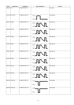
Страница 288: ...Memory Card Cover 2 Insert the Memory Card s gently into the card slot with the Panasonic logo facing to the rear Caution Installing the Memory Card s in the wrong direction may damage the connecting pins inside the machine 3 1 Re install the Memory Card Cover and the Screw to secure the Cover 2 Close the ADF Door 4 Turn the Power Switch to the I ON position Print out the Fax Parameter List see pa...

Страница 289: ... Cassette from the machine 6 Remove the Toner Cartridge from the machine 7 Remove the Paper Cassette from the Optional Feeder Unit 8 Remove the two Screws on the new Feeder Unit indicated by the arrow marks These screws are used to attach the Feeder Unit to the machine in step 12 9 Place the machine on its right side on top of a clean cloth to prevent damaging the Printer Cover 10 Plug in the conn...

Страница 290: ...e Power Cord and the Telephone Line Cable 16 Turn the Power Switch to the ON I position 17 Print some pages from the Optional Feeder Unit to confirm its operation Note The paper size guides are factory set to the Letter size If you are using either A4 or Legal size paper please adjust the paper size guides accordingly 14 13 14 ...

Страница 291: ...Telephone Line Cable 4 Remove the Document Trays 5 Remove the Paper Cassette from the machine 6 Remove the Toner Cartridge from the machine 7 Remove the Paper Cassette from the Optional Feeder Unit 8 Remove the two Screws on the new Feeder Unit indicated by the arrow marks These screws are used to attach the Feeder Unit to the machine in step 12 9 Place the machine on its right side on top of a cl...

Страница 292: ...e Power Cord and the Telephone Line Cable 16 Turn the Power Switch to the ON I position 17 Print some pages from the Optional Feeder Unit to confirm its operation Note The paper size guides are factory set to the Letter size If you are using either A4 or Legal size paper please adjust the paper size guides accordingly 14 13 14 ...

Страница 293: ...ed with this kit No Part No Description Qty Remarks 1 DZEC101411 Enhanced Printing PC Board w FRM PC Board 1 2 DZJH000059 PCB Spacer 1 3 DZQW000179 Printer Driver Disks 1 6 disks 3 2HD Floppy 4 DZSD001051 User s Guide 1 5 DZSH000080 License Agreement 1 6 DZSM000247 Installation Guide 1 This document 1 Turn the Power Switch to the OFF O position 2 Disconnect the Power Cord 3 Disconnect the Telephon...

Страница 294: ... Remove the Rear Cover 14 Insert the PCB Spacer into the hole on the PDL PC Board 15 Connect the PDL PC Board to the CN55 on the FCB PC Board 16 Secure the PDL PC Board by inserting the PCB Spacer into the hole on the FCB PC Board 17 Remove 1 Screw on the FCB PC Board and connect the GND Cable with the screw 11 10 13 12 14 15 17 16 ...

Страница 295: ... the Ethernet LAN Cable 23 Insert the Master Firmware Card that you have prepared into the machine 24 Turn the Power Switch to the ON I position 25 Perform the Service Mode 9 1 Firmware Update see page 229 26 Perform the Service Mode 6 Parameter Initialization 27 Turn the Power Switch to the OFF O position 28 Remove the Master Firmware Card 29 Re install the remaining Trays 30 Turn the Power Switc...

Страница 296: ...cross the transmission media At the opposite end Layer 7 the Application layer interfaces the network services with the applications software in use on the computer The five layers in between Data Link Network Transport Session and Presentation perform intermediate communication tasks In essence the OSI model is a framework that describes how a function from one computer is transmitted to another ...

Страница 297: ...e For the network transmission media at the Physical layer on the OSI reference model there are several cable categories available Category 5 8 wire Unshielded Twisted Pair UTP cable is commonly used Shielded Twisted Pair cables are also available The Impedance for the STP UTP Ethernet cable is 100 Ω Category 3 is also used for the 10Base T Ethernet Category Purpose 1 Voice grade telephone line 2 ...

Страница 298: ...n which circulates around the network A computer that needs to transmit must wait until it receives the token at which time the computer is permitted to transmit When the computer is done transmitting it passes the token frame to the next station on the network The first station that is powered up on a token ring network automatically becomes the active monitor station Its responsibility is to ann...

Страница 299: ...rosoft uses the term star bus topology to describe 10Base T Most significant bit Least significant bit Start De limiter SFD 1 byte P P P S M R R R End De limiter ED 1 byte P priority S Status 0 Token Frame 1 Data Frame R Reserved Most significant bit Least significant bit SFD 1 byte Access Control 1 byte Frame control 1 byte Destination MAC 6 or 2 byte Source MAC 6 or 2 byte Data FCS 4 byte ED 1 b...

Страница 300: ... future expansion due to the star topology 10 2 4 Repeater The main purpose of a repeater is to extend the maximum range for the network cabling They operate at the OSI Physical layer and do not filter or interpret the signal they merely repeat regenerate the signal passing all network traffic in all directions They perform signal amplitude delete errors and reschedule the timing Repeaters also fo...

Страница 301: ...ut it is the first two octets that make up the network address and the last two octets that make up the host ID Class C IP addresses can range in value from 192 to 223 for the first octet and the first three octets make up the host ID There are class D and E addresses as well For these addresses the first octet is a number greater than 223 These addresses are not currently available to be used and...

Страница 302: ...st significant bit starting with 127 Reserved for loop back address 1 IP 192 168 32 1 1 0 0 0 0 0 0 1 0 1 0 1 0 0 0 0 0 1 0 0 0 0 0 0 0 0 0 0 0 0 1 1 1 1 1 1 1 1 1 1 1 1 1 1 1 1 1 1 1 1 1 1 1 1 1 0 0 0 0 0 0 0 0 192 168 32 1 255 255 255 0 1 1 0 0 0 0 0 0 1 0 1 0 1 0 0 0 0 0 1 0 0 0 0 0 0 0 0 0 0 0 0 0 Subnet Mask 255 255 255 0 Network Address 192 168 32 0 IP Subnet Mask Network Address Configurati...

Страница 303: ...recedence ID Identification frame number for upper layer communication Flags Packet disassembly information Fragment Offset Offset from most significant bit Time To Live Decrement the counter until 0 every time packet pass over the router Protocol Upper layer protocol identification number ie TCP 06h UDP 11h Header Checksum Checksum is used for error checking on the header data Source Address Send...

Страница 304: ...is performs conversion of a single global IP Address from to single private IP Address 4 IP Masquerade This performs a conversion of single global IP Address from to multiple private IP Address At the same time the port number is automatically assigned Occasionally the conversion creates a bottleneck in the network overhead For a typical solution PIX Private address Internet address exchange is av...

Страница 305: ...increments the counterevery 4 msec The Server responds with an acknowledgement that increments the initial sequential number by one The ACK bit number is also changed to a 1 value The SYN can have and identical ACK response for each packet thus the server and the client can establish a connection TCP Segment in IP Datagram IP Header 20 byte Application D ata vary TCP segment IP Datagram TCP Header...

Страница 306: ...aximum separated by dots Up to 255 characters maximum including all dots Capital letters and small letters are not identical Case Sensitive The advantage of using a DNS server over a host lookup table for host name resolution is to avoid the need for a single centralized clearinghouse for all names The authority for this information can be delegated to different organizations on the network respon...

Страница 307: ...st that has the read write copy of the zone file Contact email The Internet email address of the person who maintains this file This address must be expressed with a period instead of the that is usually found in email addresses i e hostmaster rdmg mgcs mei co jp instead of hostmas ter rdmg mgcs mei co jp Serial number A version number for the zone file This number should be changed each time the ...

Страница 308: ...eb server on the same host Nicknames are useful when a well known host changes its name In this case its usually a good idea to have a CNAME record so people still using the old name will get to the right place 10 5 8 NS Name Server Record The Name Server record specifies the other name servers for a domain The syntax for a name server record is shown below domain IN NS nameserver host An example ...

Страница 309: ...that always forwards queries it cannot satisfy from its cache to a fixed list of forwarding servers instead of interacting with the name servers for the root and other domains The queries to the forwarding servers are recursive queries There may be one or more forwarding servers and they are tried in turn until the list is exhausted A Slave and forwarder configuration is typically used when you do...

Страница 310: ... one at a time For more detail please refer to the URL http www imc org rfc821 10 6 1 Mail Header Sample 10 7 ITU T 37 and RFC2305 10 7 1 Mode of operation The DX 2000 conforms to the ITU T 37 standards and RFC2305 This Internet store and forward facsimile uses approved IETF protocols for posting relaying and delivery of documents It requires no changes to Internet standards or to ITU Facsimile Re...

Страница 311: ...tempt to relay authorized email to the corresponding G3 facsimile terminals Ensure DSN for delivery failure notification Strongly recommended Use DSN for delivery failure notification Use an approved mailbox access protocol when serving multiple users Optional Translate image data into a format acceptable by the receiving G3 facsimile terminal Use a mailbox access protocol when serving a single ma...

Страница 312: ...ks S B W MH Internet Fax minimal set F B W MMR MR Internet Fax full mode J B W JBIG Internet Fax mixed mode C Color JPEG lossy Color minimal set L Color JPEG lossless grayscale One bit per color palletized color image continuos tone color and grayscale images M Color Mixed Raster Content Multiple coders and resolution within a page Baseline Fields Values Bits Per Sample 1 Compression 3 1 dimension...

Страница 313: ...re may exist valid reasons in particular circumstances to ignore a particular item but the full implications must be understood and carefully weighed before choosing a different course 4 SHOULD NOT This phrase or the phrase NOT RECOMMENDED means that there may exist valid reasons in particular circumstances when the particular behavior is acceptable or even useful but the full implications should ...

Страница 314: ...ternet Fax devices MUST be able to write minimum set TIFF files according to the rules for creating minimum set TIFF files defined in TIFF for Facsimile the S profile which is also compatible with the specifications for the minimum subset of TIFF F in F Profile for Facsimile RFC 2306 The Receiving Internet Fax devices must be able to read minimum set TIFF files Message Header Contents ...

Страница 315: ...easily reconfigurable preferably without recompiling the SMTP code The value of timer shown above are recommended by RFC1123 Opening TCP Connection TCP Port No 25 220 sv2 labo mgcs com Service ready SMTP Command Reply Procedure HELO sv2 labo mgcs com 250 ef1 labo mgcs com MAIL FROM xxx sv2 labo mgcs com 250 OK RCPT TO yyy sv2 labo mgcs com 250 OK DATA 250 Start mail out end with CR LF CR LF DATA B...

Страница 316: ...n 10 8 5 Send This command is used to initiate a mail transaction in which the mail data is delivered to one or more terminals This command is successful if the message is delivered to a terminal 10 8 6 Reset RSET This command specifies that the current mail transaction is to be aborted Any stored sender recipients and mail data must be discarded and all buffers and state tables cleared The receiv...

Страница 317: ...unavailable E g mailbox busy 451 Requested action aborted local error in processing 452 Requested action not taken insufficient system storage 500 Syntax error command unrecognized This may include errors such as command line too long 501 Syntax error in parameters or arguments 502 Command not implemented 503 Bad sequence of commands 504 Command parameter not implemented 550 Requested action not t...

Страница 318: ...ed by a CRLF pair When all lines of the response have been sent a final line is sent consisting of a termination octet decimal code 046 and a CRLF pair If any line of the multi line response begins with the termination octet the line is byte stuffed by pre pending the termination octet to that line of the response Hence a multi line response is terminated with the five octets CRLF CRLF When examin...

Страница 319: ...nt may ignore any text occurring after this reply Minimal POP3 Commands USER name valid in AUTHORIZATION state PASS string QUIT STAT valid in the TRANSACTION state LIST msg RETR msg DELE msg NOOP RSET QUIT Optional POP3 Commands APOP name digest valid in the AUTHORIZATION state TOP msg n valid in the TRANSACTION state UIDL msg POP3 Replies OK ERR Form To Sample of a POP3 Protocol Log ...

Страница 320: ...gning off Opening TCP Connection TCP Port No 110 OK POP Server ready 1898 697170952 labo mgcs com USER s50055 OK Password required for s50055 PASS xxxx OK s50055 has 2 messages 126040 octets TOP 1 1 OK 69762 octets Text DATA Text DATA PETR 1 OK 69752 octets Text DATA Text DATA Text DATA end with period OK Message 1 has been deleted DELE 2 TOP 2 1 OK 1 56288 octets Text DATA Text DATA PETR 2 OK 1 5...

Страница 321: ... must check the physical connections or wiring first Command Sample Purpose Ping Ping 192 168 1 30 Checking for physical connection between your PC and the target destination 192 168 1 30 Ipconfig all Ipconfig all Checking for current network configuration Host Name DNS server IP address Subnet Mask Default Gateway MAC address WINS etc For Windows 95 98 please type winipcfg instead of Ipconfig all...

Страница 322: ...arameters for POP receiving Yes Is there an A Record entry for the DX 2000 in the DNS table Is POP account available Yes Yes Set network parameters for POP receiving and set G3 Gateway parameters for the DX 2000 Yes No No No No Not supported Not supported Not supported Not supported Ask the Network Administrator Check the host name by using the DOS command line ping and nslookup Ask the Network Ad...

Отзывы: