260
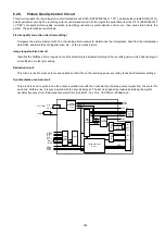
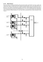
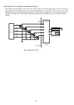
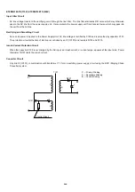
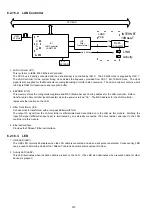
Fuser Lamp Drive Circuit
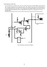
The Fuser Lamp is powered by 115 VAC. It is driven by the LVPS and controlled the FCB PC Board. When the CN32, Pin 9
(nSSR) on the LVPS goes LOW, the Fuser Lamp turns ON. This lights up the PC301 LED and activates the CR301 photo-triac,
and 115 VAC is sent to the Fuser Lamp. The time at which CR301 is actually activated depends on the 115 VAC sine wave.
When the cross-voltage for Pin 6 and Pin 4 of PC301 is other than 0 Volts (sine wave exceeds 0 volts), PC301 inhibits the
activation of the triac and turns ON the Fuser Lamp.
99
CN32
CN67
+24V
R304
4
2
1
PC301
nSSR
R303
CR301
2
1
C302
R302
C301
R301
L301
1
2
CN35
CN34
CN34
H
CN35
LVPS
Fuser Lamp
Fuse
Thermostat
Thermal Fuse
ACI PCB
3
LPC PCB
6
Fuser Lamp Drive Circuit Diagram
2
1
Содержание Panafax DX-2000
Страница 2: ......
Страница 27: ...27 9 1 Screw 19 10 Release two Latch Hooks 11 Remove the SNS Assembly 121 9 10 11 ...
Страница 49: ...49 2 15 Screw Identification Template ...
Страница 56: ...56 3 7 2 Printer Circuit 429 650 622 744 607 665 555 506 432 408 405 433 502 610 610 610 621 507 507 639 ...
Страница 57: ...57 3 7 3 Option Cassette Circuit 555 748 728 744 928 953 730 731 731 952 944 930 931 931 ...
Страница 58: ...58 3 7 4 LAN Control Circuit 522 CN50 1102 1104 1101 N C N C RD N C N C RD TD TD ...
Страница 59: ...59 3 7 5 Page Description Language Printer Interface Kit ...
Страница 287: ...314 B Supplies Order No Picture Description DZHT000004 Verification Stamp UG 3313 Toner Cartridge ...

