322
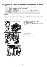
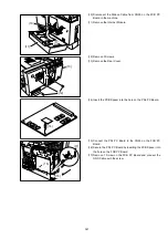
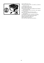
(18) Re-install the Rear Cover.
(19) Connect the Ribbon Cable to the CN50 on the FCB PC
Board in the machine.
(20) Re-install the Internet Module.
(21) Re-install the Sub Rear Cover.
(22) Re-connect the Power Cord, the Telephone Line Cable and
the Ethernet LAN Cable.
(23) Insert the Master Firmware Card that you have prepared
into the machine.
(24) Turn the Power Switch to the ON (I) position.
(25) Perform the Service Mode 9-1 (Firmware Update).
(see page 229)
(26) Perform the Service Mode 6 (Parameter Initialization).
(27) Turn the Power Switch to the OFF (O) position.
(28) Remove the Master Firmware Card.
(29) Re-install the remaining Trays.
(30) Turn the Power Switch to the ON (I) position.
(22)
(22)
(24)
(22)
Содержание Panafax DX-2000
Страница 2: ......
Страница 27: ...27 9 1 Screw 19 10 Release two Latch Hooks 11 Remove the SNS Assembly 121 9 10 11 ...
Страница 49: ...49 2 15 Screw Identification Template ...
Страница 56: ...56 3 7 2 Printer Circuit 429 650 622 744 607 665 555 506 432 408 405 433 502 610 610 610 621 507 507 639 ...
Страница 57: ...57 3 7 3 Option Cassette Circuit 555 748 728 744 928 953 730 731 731 952 944 930 931 931 ...
Страница 58: ...58 3 7 4 LAN Control Circuit 522 CN50 1102 1104 1101 N C N C RD N C N C RD TD TD ...
Страница 59: ...59 3 7 5 Page Description Language Printer Interface Kit ...
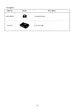
Страница 287: ...314 B Supplies Order No Picture Description DZHT000004 Verification Stamp UG 3313 Toner Cartridge ...

