22
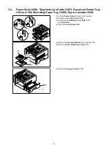
2.3.
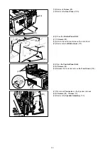
Sub Rear Cover (114), Internet Enclosure (1103), LANB PC Board (1102),
LANC PC Board (1101), FRM PC Board (1104), Rear Cover (108), Left
Side Cover (107), Front Cover (105), Speaker (133)
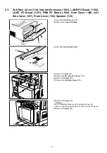
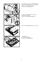
(1) Open the Printer Cover (122).
(2) Remove the Toner Cartridge.
(3) Open the Control Panel Unit.
(4) Remove 1 Screw (B1).
(5) Remove the Memory Card Cover (115).
(6) Remove 4 Screws (B1).
(7) Remove the Sub Rear Cover (114).
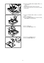
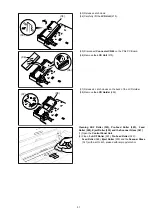
(8) Remove 2 Screws (23).
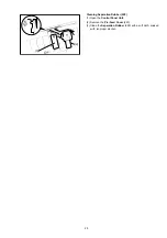
Caution:
When re-installing these machine screws (screws with
washers), ensure they are placed on the top of the enclosure.
(9) Remove 2 Screws (B1).
(1)
(2)
(3)
(7)
(6)
(4)
(5)
(6)
(6)
(9)
(8)
Содержание Panafax DX-2000
Страница 2: ......
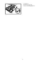
Страница 27: ...27 9 1 Screw 19 10 Release two Latch Hooks 11 Remove the SNS Assembly 121 9 10 11 ...
Страница 49: ...49 2 15 Screw Identification Template ...
Страница 56: ...56 3 7 2 Printer Circuit 429 650 622 744 607 665 555 506 432 408 405 433 502 610 610 610 621 507 507 639 ...
Страница 57: ...57 3 7 3 Option Cassette Circuit 555 748 728 744 928 953 730 731 731 952 944 930 931 931 ...
Страница 58: ...58 3 7 4 LAN Control Circuit 522 CN50 1102 1104 1101 N C N C RD N C N C RD TD TD ...
Страница 59: ...59 3 7 5 Page Description Language Printer Interface Kit ...
Страница 287: ...314 B Supplies Order No Picture Description DZHT000004 Verification Stamp UG 3313 Toner Cartridge ...

