


182
Cha
p
ter 8
T
OOL
8.3 Reference Point
Reference Point is one coordinate value that can be specified per product type and memory. This point is
quoted and incorporated to a numeric calculation and incorporated and can be displayed as a
intersection of X-and Y-axis on the monitor screen during inspection, so that you can check not only the
position of the point visually but also inspection data when adjusting the position of an object. Refer to
page 196 for setting the items displayed in RUN mode
1. Select "TOOL" > "Ref.Point" from the menu bar.
The Ref. Point menu is displayed. Press the B key to switch the display to Memory/Live or the background
to Solid/Translucent.
2. Select a memory which you want to assign to the reference coordinates.
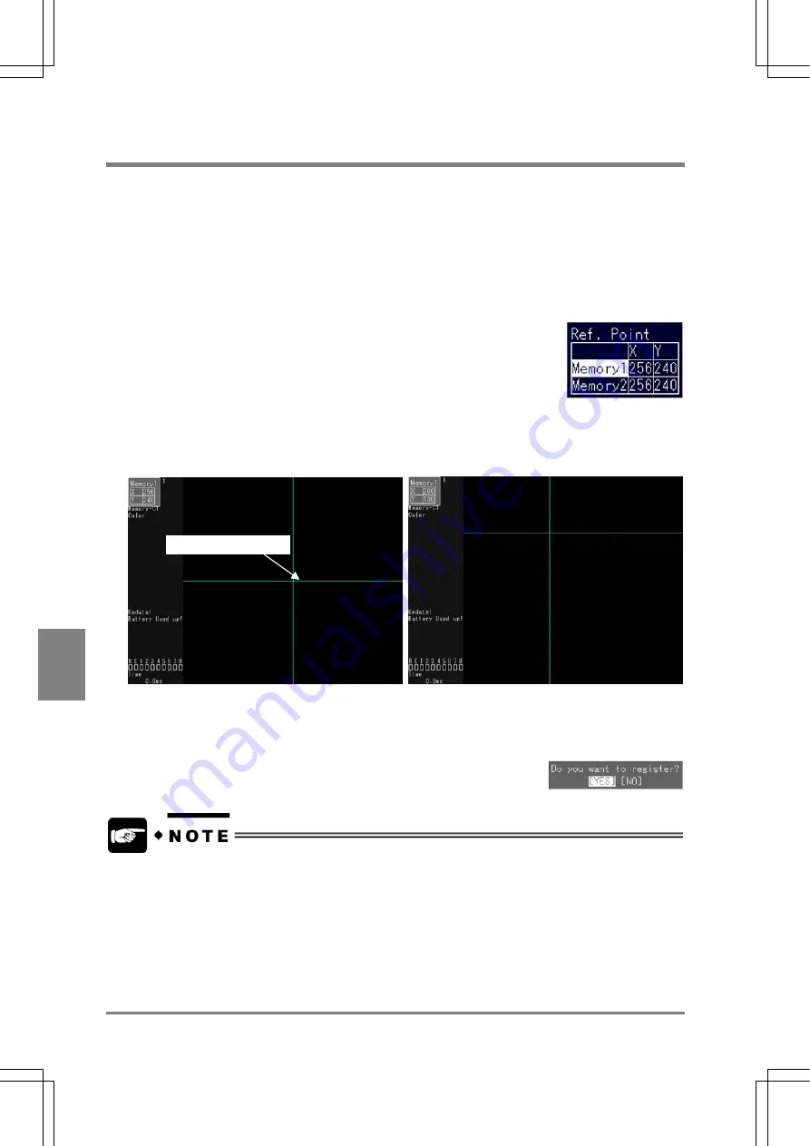
The blue cross lines are displayed in the image display area. The point at which the x and y axes are
intersected is a reference point. The coordinate values of the reference point are displayed in the upper
part of the image display area.
3. Move the cursor to the desired position by tilting the ENTER key and press the ENTER key to
fix the position.
When the dialog message is displayed, select "YES" to continue.
•
If you set a reference coordinates when setting the display in RUN mode, the reference
coordinates of both Memory 1 and Memory 2 are displayed. But, you cannot display the
reference point of either memory 1 or 2.
•
The reference points of Memory 1 and Memory 2 are preset at the middle point (256, 240) of
the screen monitor. You can change the reference points in the steps above, but you cannot
delete the points.
Reference coordinates
Содержание Micro-Imagechecker AX40
Страница 9: ...1 Names and Functions of Parts Chapter 1 Chapter 1 Names and Functions of Parts ...
Страница 15: ...7 Installation and Wiring Chapter 2 Chapter 2 Installation and Wiring ...
Страница 25: ...17 Input and Output Interface Ports Chapter 3 Chapter 3 Input and Output Interface Ports ...
Страница 42: ......
Страница 55: ...47 Chapter 5 Procedure for Setting Inspection Conditions Chapter 5 Procedure for Setting Inspection Conditions ...
Страница 70: ......
Страница 94: ...86 Setting Checkers Chapter 6 6 7 Gray Edge 6 7 1 Menu Options ...
Страница 108: ...100 Setting Checkers Chapter 6 6 9 Smart Matching 6 9 1 Menu Options ...
Страница 184: ......
Страница 185: ...177 TOOL Chapter 8 Chapter 8 TOOL ...
Страница 192: ......
Страница 193: ...185 Environment Settings Chapter 9 Chapter 9 Environment Settings ...
Страница 215: ...207 Chapter 10 Parallel Communication Chapter 10 Parallel Communication ...
Страница 225: ...217 Chapter 11 RS232C Communication Chapter 11 RS232C Communication ...
Страница 255: ...247 Chapter 12 Ethernet Communication Chapter 12 Ethernet Communication ...
Страница 261: ...253 Chapter 13 Using a CF Card Chapter 13 Using a CF Card ...
Страница 273: ...265 Chapter 14 Information on AX40 and Help Function Setting Chapter 14 Information on AX40 and Help Function Setting ...
Страница 279: ...271 Chapter 15 Troubleshooting Chapter 15 Troubleshooting ...
Страница 283: ...275 Chapter 16 Specifications and Product Numbers Chapter 16 Specifications and Product Numbers ...
Страница 291: ...283 Chapter 16 Specifications and Product Numbers 16 3 Dimensions AX40 Random Color Camera Product number ANMX8310 ...
Страница 292: ...284 Specifications and Product Numbers Chapter 16 Camera Cable Keypad ...
Страница 293: ...285 Chapter 16 Specifications and Product Numbers Lens ANB846NL ANB845NL ANB847L ANB843L ANM8850 ANM88501 Unit mm ...
Страница 294: ...286 Specifications and Product Numbers Chapter 16 ANM88161 ANM88251 ANB842NL Unit mm ...
Страница 296: ...288 Record of Changes Manual No Date Description of Changes ARCT1F462E March 2009 First Edition ...


