


– 48 –
Chapter 4 Preparations — Various settings
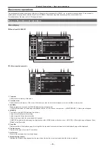
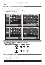
Setting signal formats
Select the system format.
1
Select the <SYS> button
→
[SYSTEM]
→
[Video] tab.
2
Set [Video Format] in the [Video Format] column.
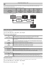
Setting sync signals
Set the external sync signals supplied to the <REF> terminal of the XPT Unit and output phase.
1
Select the <SYS> button
→
[SYSTEM]
→
[Video] tab.
2
Set the output phase in the [Output Phase] column.
3
Select a sync signal in [Sync] in the [Reference] column.
f
Selects from [BB], [BB Advanced], [Tri-level sync], [Internal], and [ST2059].
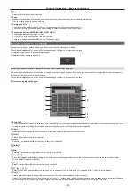
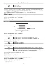
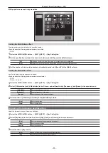
Setting input signals
Various input signal settings
Make various settings for SDI input signals.
f
For details, refer to “Setting input signals”.
1
Select the <IN OUT> button
→
[SDI IN 1] to [SDI IN 20]
→
[Frame Buffer]/[Status] tab, and make the following settings.
[Frame Buffer] tab
Sets the frame synchronizer, and freeze effects.
[Status] tab
Displays the information on the images for SDI input signals.
2
Select the <CC> button
→
[C/C IN 1-5] to [C/C IN 16-20]
→
select the tab you want to set, and then set the color collector.
f
Make the settings for color correctors built into the <SDI IN 1> to <SDI IN 20> terminals.
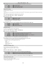
Setting video source names
Set source names displayed on the source name display panels of the Control Panel and the MultiView display.
f
For details, refer to “Setting the source name”.
1
Select the <NAME> button
→
[SDI IN]/[IP IN]/[INTERNAL]/[ME]/[DSK]/[AUX]/[MV]
→
[Panel Name]/[MV Name] tab, and make the
settings for source names, etc.
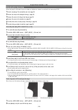
Setting video source links
Make the settings for links of key fills and key sources handled as keys. When key fills (key sources) are selected with the KEY bus crosspoint buttons,
the linked key sources (key fills) are selected automatically. Select which of key fill and key source to be set as a master from the menu. The same
setting can be used for the AUX bus link setting.
f
For details, refer to “Selecting the key source”.
1
Select the <OPR> button
→
[SOURCE LINK]
→
[Key Assign] tab.
2
Assign the items in the slave list at the right row to the items in the master list at the left row.
f
With that, key fill and key source link settings are complete.
f
When enabling/disabling link settings with the AUX bus link settings, proceed to the step
.
3
Select the [AUX Bus Link] tab.
4
Select an item in [AUX1/2 Link] to [AUX15/16 Link] in the [AUX1-10 Link]/[AUX11-16 Link] column.
[ON]
Enables link settings.
[OFF]
Disables link settings.
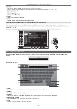
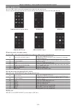
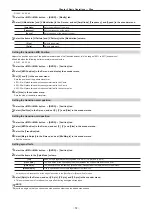
Button settings
Assigning video sources to buttons
External video input signals and internally generated signals can be assigned to the crosspoint buttons (the PGM/A, PST/B, and KEY bus crosspoint
buttons) in the crosspoint area.
f
For details, refer to “Assigning signals to buttons”.
1
Select the <PANEL> button
→
[XPT ASSIGN]
→
[Panel1]/[Panel2]/[Panel3] tab, and make the following settings.
[Panel1] tab
Assigns the control panel 1.
[Panel2] tab
Assigns the control panel 2 (second Control Panel).
[Panel3] tab
Assigns the control panel 3 (third Control Panel).
Содержание Live Production Suite Series
Страница 5: ...Please read this chapter and check the accessories before use Chapter 1 Overview ...
Страница 11: ...This chapter describes installation and connection Chapter 2 Installation and Connection ...
Страница 33: ...This chapter describes basic operations and matters to be performed prior to use Chapter 4 Preparations ...
Страница 50: ...This chapter describes menu operations Chapter 5 Basic Operations ...
Страница 107: ...This chapter describes the input output signal settings Chapter 6 Input Output Signal Settings ...
Страница 112: ... 112 Chapter 6 Input Output Signal Settings Setting MultiView displays f f Set the marker size ...
Страница 113: ...This chapter describes the configuration of operations Chapter 7 Configuring Operations ...
Страница 122: ...This chapter describes how to operate system menus Chapter 8 System Menu ...
Страница 136: ...This chapter describes plug in functions Chapter 9 External Interfaces ...
Страница 138: ...This chapter describes the dimensions and specifications of this product Chapter 10 Specifications ...
Страница 139: ... 139 Chapter 10 Specifications Dimensions Dimensions Dimensions of the Gateway Unit AV LSG10 Unit mm inch ...
Страница 140: ... 140 Chapter 10 Specifications Dimensions Dimensions of the XPT Unit AV LSX10 Unit mm inch ...
Страница 141: ... 141 Chapter 10 Specifications Dimensions Dimensions of the ME Unit AV LSM10 Unit mm inch ...
Страница 142: ... 142 Chapter 10 Specifications Dimensions Dimensions of the System Manager Unit AV LSS10 Unit mm inch ...
Страница 153: ...This chapter describes the setting menu table and terms Chapter 11 Appendix ...
Страница 176: ...Web Site https www panasonic com Panasonic Corporation 2020 ...


