– 133 –
Chapter 8 System Menu — Maintenance settings
f
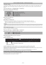
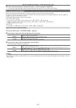
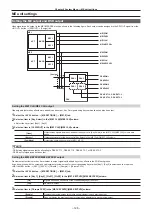
A log file is saved in an internal storage of the computer.
f
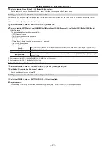
Enter the IP address for the <LAN> terminal of the Live Production Suite system in the place of “192.168.0.10”. If the address has been changed
from the default setting (192.168.0.90), enter the changed value. For details on IP address setting, refer to “Configuring the network for the Live
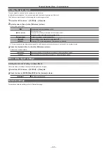
Initialization
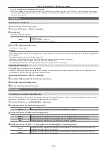
Initializing the setting data
The setting data can be reset to factory settings.
1
Select the <SYS> button
→
[BOOT]
→
[Boot] tab.
2
Select [Initial].
f
Select the mode to be initialized.
[Initial]
Initializes the unit.
f
Plug-in software is not deleted.
f
Network setting values are not initialized.
3
Select [OK] in the confirmation screen.
f
Initialize the settings data.
@
@
NOTE
t
When settings data is initialized, the still image data and moving image data saved in the video memory is deleted. Data stored in the Storage Module
is not initialized.
t
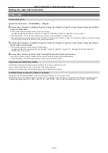
The setting of date and time is not initialized. (page 134)
t
Initialization cannot be performed during video (Clip) recording/playback or during event memory playback.
t
When you have deleted plug-in software, turn off the power, and restart the unit.
t
There may be differences in the items displayed depending on the settings at the time of delivery.
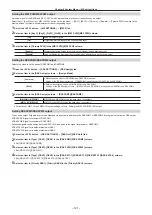
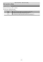
Initializing the fader lever
The transition range of the fader lever can be initialized.
f
Initialization should be performed when the fader lever becomes out of adjustment by moving the installation location, etc., and transitions are not
completed even if the fader lever has been pushed as far as it will go.
1
Select the <SYS> button
→
[BOOT]
→
[Boot] tab.
2
Select [Panel1]/[Panel2]/[Panel3] in the [Fader Initial] column.
3
Select [OK] in the confirmation screen.
4
Move the fader lever back and forth once.
Maintenance
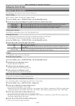
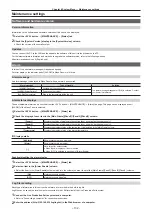
Confirmation of cumulative operating time
Confirm rough indication of the cumulative operating time of the Live Production Suite system, and the cumulative operating time of the power supply
and cooling fan installed in the Live Production Suite system and the Control Panel.
1
Select the <SYS> button
→
[MAINTENANCE]
→
[Mainte] tab
2
Confirm each item in the [System Running] column.
[System]
Displays the count-up time when the Live Production Suite system is in operation.
3
Confirm each item in the [Main Frame Running] column.
[Power 1]
Displays the count-up time when the power supply 1 of the Live Production Suite system is in operation.
[Power 2]
Displays the count-up time when the power supply 2 of the Live Production Suite system is in operation.
[Fan]
Displays the count-up time when the Live Production Suite system is in operation.
4
Confirm each item in the [Panel 1 Connecting]/[Panel 2 Connecting]/[Panel 3 Connecting] column.
[Power 1]
Displays the count-up time when the control panels are connected to the LAN terminal of the Live Production Suite
system and each power supply 1 is in operation.
[Power 2]
Displays the count-up time when the control panels are connected to the LAN terminal of the Live Production Suite
system and each power supply 2 is in operation.
Содержание Live Production Suite Series
Страница 5: ...Please read this chapter and check the accessories before use Chapter 1 Overview ...
Страница 11: ...This chapter describes installation and connection Chapter 2 Installation and Connection ...
Страница 33: ...This chapter describes basic operations and matters to be performed prior to use Chapter 4 Preparations ...
Страница 50: ...This chapter describes menu operations Chapter 5 Basic Operations ...
Страница 107: ...This chapter describes the input output signal settings Chapter 6 Input Output Signal Settings ...
Страница 112: ... 112 Chapter 6 Input Output Signal Settings Setting MultiView displays f f Set the marker size ...
Страница 113: ...This chapter describes the configuration of operations Chapter 7 Configuring Operations ...
Страница 122: ...This chapter describes how to operate system menus Chapter 8 System Menu ...
Страница 136: ...This chapter describes plug in functions Chapter 9 External Interfaces ...
Страница 138: ...This chapter describes the dimensions and specifications of this product Chapter 10 Specifications ...
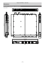
Страница 139: ... 139 Chapter 10 Specifications Dimensions Dimensions Dimensions of the Gateway Unit AV LSG10 Unit mm inch ...
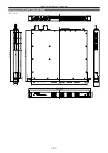
Страница 140: ... 140 Chapter 10 Specifications Dimensions Dimensions of the XPT Unit AV LSX10 Unit mm inch ...
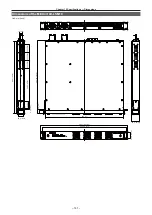
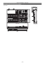
Страница 141: ... 141 Chapter 10 Specifications Dimensions Dimensions of the ME Unit AV LSM10 Unit mm inch ...
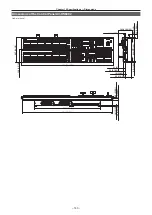
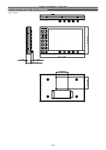
Страница 142: ... 142 Chapter 10 Specifications Dimensions Dimensions of the System Manager Unit AV LSS10 Unit mm inch ...
Страница 153: ...This chapter describes the setting menu table and terms Chapter 11 Appendix ...
Страница 176: ...Web Site https www panasonic com Panasonic Corporation 2020 ...

