– 52 –
Chapter 5 Basic Operations — Background transition
f
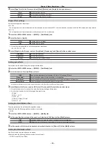
Set the transition time.
@
@
NOTE
t
r
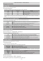
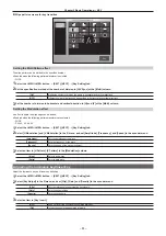
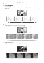
Setting the start and end points of a transition
1
Select the <ME1>/<ME2> button
→
[BKGD]
→
[Transition] tab.
2
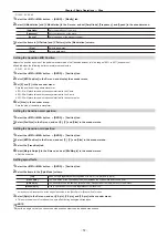
Select [Margin Adjust] in the R menu, and set [Start Point] and [End Point] in the encoder menu.
[Start Point]
Sets the start point for the background transition.
The background transition will start after the start point of the manual transition or the auto transition when a value
larger than 0 is set for [Start Point]. At this time, the lamp for start point of the fader lever will blink in the transition status
display.
[End Point]
Sets the end point for background transition.
The background transition will complete before the end point of the manual transition or the auto transition when a value
larger than 0 is set for [End Point]. At this time, the lamp for end point of the fader lever will blink in the transition status
display.
f
While the <PATT LIMIT> button is lighting up, the settings of [Start Point] and [End Point] are disabled.
r
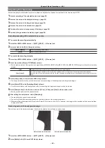
<NAM/CMIX> button setting
Set the behavior of background transition when the <MIX> button is on.
1
Select the <ME1>/<ME2> button
→
[BKGD]
→
[Transition] tab.
2
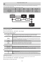
Select the items in [NAM/CMIX] and [Type] in the [NAM/CMIX] column.
f
The settings for [NAM/CMIX] are linked to the lighting status of the <NAM/CMIX> button.
[NAM/CMIX] items
[Type] items
Image operations
[OFF]
―
Images switch by overlapping.
During the transition, the output total of the A bus and B bus is kept at
100%.
[ON]
[NAM]
Switches the images in the A bus/B bus with non-additive mixing.
It will be high luminance with the A bus at 100% and the B bus at 100%
when the fader lever is positioned midway.
[CMIX]
The images are mid way between the A bus and B bus images,
becoming a MIX composition that is the color set in [CMIX Matte] in the
R menu. (Color mix composition)
r
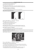
Transition curve settings
1
Select the <ME1>/<ME2> button
→
[BKGD]
→
[Transition] tab.
2
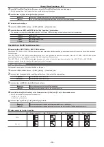
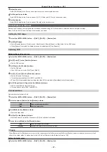
Select the items in [MIX] and [WIPE] in the [Trans Curve] column.
f
The transition curve can be set individually for each of MIX and WIPE according to the selection state of the transition type.
[Linear]
Straight line
[S Soft]
A shallow S curve
[S Mid]
An intermediate S curve
[S Hard]
A deep S curve
Содержание Live Production Suite Series
Страница 5: ...Please read this chapter and check the accessories before use Chapter 1 Overview ...
Страница 11: ...This chapter describes installation and connection Chapter 2 Installation and Connection ...
Страница 33: ...This chapter describes basic operations and matters to be performed prior to use Chapter 4 Preparations ...
Страница 50: ...This chapter describes menu operations Chapter 5 Basic Operations ...
Страница 107: ...This chapter describes the input output signal settings Chapter 6 Input Output Signal Settings ...
Страница 112: ... 112 Chapter 6 Input Output Signal Settings Setting MultiView displays f f Set the marker size ...
Страница 113: ...This chapter describes the configuration of operations Chapter 7 Configuring Operations ...
Страница 122: ...This chapter describes how to operate system menus Chapter 8 System Menu ...
Страница 136: ...This chapter describes plug in functions Chapter 9 External Interfaces ...
Страница 138: ...This chapter describes the dimensions and specifications of this product Chapter 10 Specifications ...
Страница 139: ... 139 Chapter 10 Specifications Dimensions Dimensions Dimensions of the Gateway Unit AV LSG10 Unit mm inch ...
Страница 140: ... 140 Chapter 10 Specifications Dimensions Dimensions of the XPT Unit AV LSX10 Unit mm inch ...
Страница 141: ... 141 Chapter 10 Specifications Dimensions Dimensions of the ME Unit AV LSM10 Unit mm inch ...
Страница 142: ... 142 Chapter 10 Specifications Dimensions Dimensions of the System Manager Unit AV LSS10 Unit mm inch ...
Страница 153: ...This chapter describes the setting menu table and terms Chapter 11 Appendix ...
Страница 176: ...Web Site https www panasonic com Panasonic Corporation 2020 ...

