– 30 –
Chapter 3 Part Names and Functions — Control Panel AV-HS60C2/AV-HS60C4
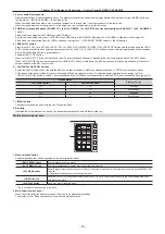
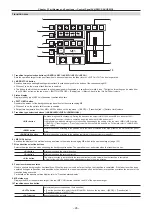
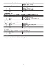
7 <COM1 (M)> terminal (connector: D-sub 9-pin (female), inch screw/signal: RS-422)
Used for master connection of external devices.
This terminal cannot be used with the Live Production Suite series.
8 <COM2 (RS-232)> terminal (connector: D-sub 9-pin (male), inch screw/signal: RS-232)
Used to control external device.
This terminal cannot be used with the Live Production Suite series.
9 <GPI I/O> terminal (connector: D-sub 25-pin (female), inch screw/signal: GPI)
Equipped with 8 contact input ports (GPI IN) that control the unit externally, 10 output ports (GPI OUT) that output tallies or status information from
the unit, and an alarm output port (ALARM OUT).
This terminal cannot be used with the Live Production Suite series.
10 <F1>/<F2> terminals
(Fuse)
11 <SIGNAL GND> terminal (signal: SG)
Connects to the ground of the system.
@
@
NOTE
t
For the cable connecting to the <DVI-D> terminal, use a double-shielded cable.
t
For the cable connecting to the <MAIN FRAME> terminal, use a shielded cable.
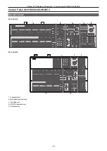
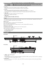
Side (right)
r
AV-HS60C2
12
(Front)
(Rear)
r
AV-HS60C4
1 2
(Front)
(Rear)
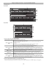
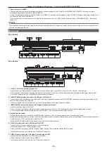
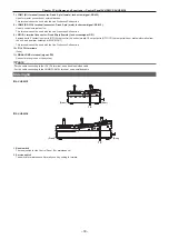
1 Reset switch
The reset switch for the Control Panel. (For maintenance)
2 Service switch
The switch for maintenance. Normally use it by setting to forward.
Содержание Live Production Suite Series
Страница 5: ...Please read this chapter and check the accessories before use Chapter 1 Overview ...
Страница 11: ...This chapter describes installation and connection Chapter 2 Installation and Connection ...
Страница 33: ...This chapter describes basic operations and matters to be performed prior to use Chapter 4 Preparations ...
Страница 50: ...This chapter describes menu operations Chapter 5 Basic Operations ...
Страница 107: ...This chapter describes the input output signal settings Chapter 6 Input Output Signal Settings ...
Страница 112: ... 112 Chapter 6 Input Output Signal Settings Setting MultiView displays f f Set the marker size ...
Страница 113: ...This chapter describes the configuration of operations Chapter 7 Configuring Operations ...
Страница 122: ...This chapter describes how to operate system menus Chapter 8 System Menu ...
Страница 136: ...This chapter describes plug in functions Chapter 9 External Interfaces ...
Страница 138: ...This chapter describes the dimensions and specifications of this product Chapter 10 Specifications ...
Страница 139: ... 139 Chapter 10 Specifications Dimensions Dimensions Dimensions of the Gateway Unit AV LSG10 Unit mm inch ...
Страница 140: ... 140 Chapter 10 Specifications Dimensions Dimensions of the XPT Unit AV LSX10 Unit mm inch ...
Страница 141: ... 141 Chapter 10 Specifications Dimensions Dimensions of the ME Unit AV LSM10 Unit mm inch ...
Страница 142: ... 142 Chapter 10 Specifications Dimensions Dimensions of the System Manager Unit AV LSS10 Unit mm inch ...
Страница 153: ...This chapter describes the setting menu table and terms Chapter 11 Appendix ...
Страница 176: ...Web Site https www panasonic com Panasonic Corporation 2020 ...

