– 51 –
Chapter 5 Basic Operations — Background transition
Background transition
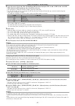
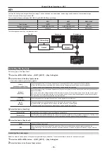
Selecting a bus
Select sources to be used for background transitions.
1
Press the crosspoint buttons.
f
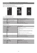
Depending on the operating status, the buttons pressed will light in one of three color patterns.
Type
Color when lit*
Description
High tally
[Red]
Lights when the selected source is included in the on-air output.
Low tally
[Yellow]
Lights when the selected source is not included in the on-air output but
included in the program output.
Preset tally
[Green]
Lights when the selected source is included in neither the on-air output
nor the program output.
* Indicates the default colors. To change the colors, select the <PANEL> button on the top menu
→
[BUTTON COLOR]
→
[Settings] tab
→
[Select Button]
column.
f
The color when lit for the buttons not selected can also be set by source or by block. (page 129)
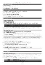
Selecting a bus using the SHIFT function
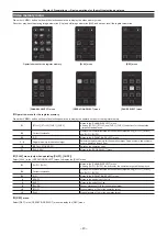
The SHIFT function is to switch pages of the crosspoint buttons with the <2nd PAGE>/<3rd PAGE> button.
There are two ways to perform the SHIFT function.
All SHIFT
Use the <2nd PAGE>/<3rd PAGE> button to switch all pages of buses included in the corresponding ME at once.
Single SHIFT
Assign the <2nd PAGE>/<3rd PAGE> button to the crosspoint buttons to switch pages. (page 115)
Using the assigned button, only the pages of individual bas can be switched.
The <2nd PAGE>/<3rd PAGE> buttons are available in two modes. The setting can be changed using the menu. (page 118)
[Normal]
The buttons are turned on only while they are pressed.
[Page Lock]
The buttons are turned on and off each time they are pressed.
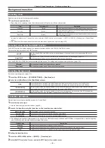
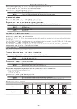
Selecting the bus mode
Set the bus operating mode.
(
)
1
Select the <OPR> button
→
[OTHER SETTINGS]
→
[Bus Mode] tab.
2
Set an item in [Bus Mode] in the [Bus Mode] column.
[A/B]
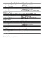
When the fader lever is at side A, the signals selected on the A bus are used as the source of the PGM bus.
When the fader lever is at side B, the signals selected on the B bus are used as the source of the PGM bus.
[PGM-A/PST-B]
Using a flip-flop system, the signals selected on the A bus are always used as the source of the PGM bus, and the
signals selected on the B bus are always used as the source of the PST bus.
[PGM-B/PST-A]
Using a flip-flop system, the signals selected on the B bus are always used as the source of the PGM bus, and the
signals selected on the A bus are always used as the source of the PST bus.
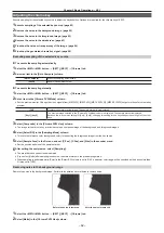
Transition operations
Operate transitions using the transition area on the Control Panel.
1
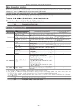
Select the transition type.
f
Use the transition type selection buttons. (page 26)
2
Execute the transition using the fader lever or the transition execution button.
Manual transition
Move the fader lever to execute the transition.
Auto transition
Press the <AUTO> button to execute the transition automatically.
Cut transition
Press the <CUT> button to execute the transition instantaneously.
f
The lighting of the bus name display panel to the right of the PGM/A bus crosspoint buttons and PST/B bus crosspoint buttons, whether High tally
color or Low tally color, indicates the output status of the buses.
Lighting color
Description
High tally
Lights when the relevant bus is included in the on-air output.
Low tally
Lights when the relevant bus is not included in the on-air output but included in the program output.
Off
Lights when the relevant bus is included in neither the on-air output nor the program output.
r
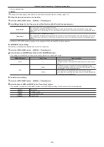
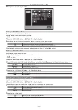
Setting the transition time
1
Select the <ME1>/<ME2> button
→
[BKGD]
→
[Transition] tab.
2
Select [AUTO Time] in the R menu, and set [AUTO Time] in the encoder menu.
Содержание Live Production Suite Series
Страница 5: ...Please read this chapter and check the accessories before use Chapter 1 Overview ...
Страница 11: ...This chapter describes installation and connection Chapter 2 Installation and Connection ...
Страница 33: ...This chapter describes basic operations and matters to be performed prior to use Chapter 4 Preparations ...
Страница 50: ...This chapter describes menu operations Chapter 5 Basic Operations ...
Страница 107: ...This chapter describes the input output signal settings Chapter 6 Input Output Signal Settings ...
Страница 112: ... 112 Chapter 6 Input Output Signal Settings Setting MultiView displays f f Set the marker size ...
Страница 113: ...This chapter describes the configuration of operations Chapter 7 Configuring Operations ...
Страница 122: ...This chapter describes how to operate system menus Chapter 8 System Menu ...
Страница 136: ...This chapter describes plug in functions Chapter 9 External Interfaces ...
Страница 138: ...This chapter describes the dimensions and specifications of this product Chapter 10 Specifications ...
Страница 139: ... 139 Chapter 10 Specifications Dimensions Dimensions Dimensions of the Gateway Unit AV LSG10 Unit mm inch ...
Страница 140: ... 140 Chapter 10 Specifications Dimensions Dimensions of the XPT Unit AV LSX10 Unit mm inch ...
Страница 141: ... 141 Chapter 10 Specifications Dimensions Dimensions of the ME Unit AV LSM10 Unit mm inch ...
Страница 142: ... 142 Chapter 10 Specifications Dimensions Dimensions of the System Manager Unit AV LSS10 Unit mm inch ...
Страница 153: ...This chapter describes the setting menu table and terms Chapter 11 Appendix ...
Страница 176: ...Web Site https www panasonic com Panasonic Corporation 2020 ...

