– 54 –
Chapter 5 Basic Operations — Background transition
f
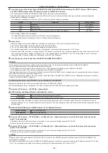
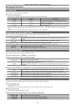
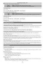
The bus tallies on the right of the PGM/A bus crosspoint buttons and the PST/B bus crosspoint buttons indicate the output status of the program
bus.
Lighting color
Description
Red
Lights when the relevant bus is included in the on-air output.
Amber
Lights when the relevant bus is not included in the on-air output but included in the program output.
Off
Lights when the relevant bus is included in neither the on-air output nor the program output.
r
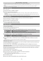
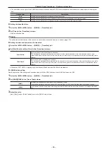
Setting the transition time
1
Select the <ME1>/<ME2> button
→
[BKGD]
→
[Transition] tab.
2
Set [Time] in the [Transition] column.
f
Set the transition time.
@
@
NOTE
t
r
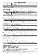
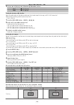
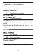
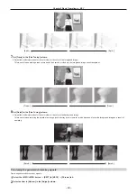
Setting the start and end points of a transition
1
Select the <ME1>/<ME2> button
→
[BKGD]
→
[Transition] tab.
2
Set [Start Point] and [End Point] in the [Transition] column.
[Start Point]
Sets the start point for the background transition.
The background transition will start after the start point of the manual transition or the auto transition when a value
larger than 0 is set for [Start Point]. At this time, the lamp for start point of the fader lever will blink in the transition status
display.
[End Point]
Sets the end point for background transition.
The background transition will complete before the end point of the manual transition or the auto transition when a value
larger than 0 is set for [End Point]. At this time, the lamp for end point of the fader lever will blink in the transition status
display.
f
While the <PATT LIMIT> is lighting up, the settings of [Start Point] and [End Point] are disabled.
r
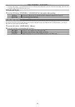
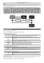
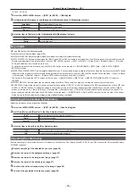
<NAM> button setting
Sets the operation of the background transition when both the <MIX> button and the <NAM> button are set ON.
1
Select the <ME1>/<ME2> button
→
[BKGD]
→
[Transition] tab.
2
Set [NAM]/[CMIX] in the [Trans Type] column.
[NAM]
Switches the images in the A bus/B bus with non-additive mixing.
It will be high luminance with the A bus at 100% and the B bus at 100% when the fader lever is positioned midway.
[CMIX]
It will perform the MIX mixing (color mix mixing) set in the [CMIX Color] column at the midway of the images of A bus/B
bus.
3
Adjust the color.
[Hue], [Sat], [Lum] or [Color Palette] is set in the [CMIX Color] column.
Содержание AV-HS60C1E
Страница 5: ...Please read this chapter and check the accessories before use Chapter 1 Overview ...
Страница 32: ...This chapter describes basic operations and matters to be performed prior to use Chapter 4 Preparations ...
Страница 52: ...This chapter describes menu operations Chapter 5 Basic Operations ...
Страница 118: ...This chapter describes the input output signal settings Chapter 6 Input Output Signal Settings ...
Страница 129: ...This chapter describes how to operate the CONFIG menu displayed when the CONF button is pressed Chapter 7 CONFIG Menu ...
Страница 140: ...This chapter describes how to operate the system menu displayed when the SYS button is pressed Chapter 8 System Menu ...
Страница 162: ...This chapter describes the difference with the Standard mode Chapter 9 3G mode 4K mode ...
Страница 168: ...This chapter describes the terminals and signals of the unit Chapter 10 External Interfaces ...
Страница 173: ...This chapter describes the dimensions and specifications of this product Chapter 11 Specifications ...
Страница 184: ...This chapter describes the setting menu table and terms Chapter 12 Appendix ...
Страница 206: ...Web Site http www panasonic com Panasonic Corporation 2014 ...


