– 154 –
Chapter 8 System Menu — Setting the external connection
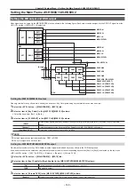
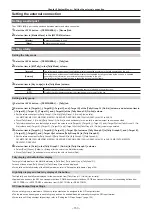
Setting the GPI input/output
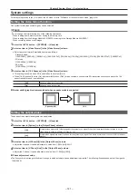
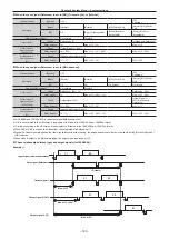
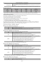
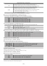
Set the GPI input/output port of the Main Frame AV-HS60U1/AV-HS60U2, Control Panel AV-HS60C1/AV-HS60C2/AV-HS60C4.
Setting the GPI input port
Functions can be assigned and externally controlled through the GPI input ports.
f
The GPI input ports are the pins 1 to 18 of the <GPI IN> terminal on the Main Frame AV-HS60U1/AV-HS60U2, and the pins 1 to 8 of the <GPI I/O>
terminal on the Control Panel AV-HS60C1/AV-HS60C2/AV-HS60C4. (page 169)
1
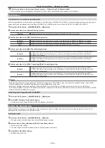
Select the <SYS> button
→
[PERIPHERAL]
→
[GPI IN] tab.
2
Select [ID] and select an item.
f
Select [Mainframe], [MainPanel], [SubPanel1], or [SubPanel2] as the setting target.
3
Select the port where you want to assign a function from the port list in the left column.
f
Select [Select] to filter the port list in the left column. You can select [All], [GPI In1‑6], [GPI In7‑12], or [GPI In13‑18].
4
Select the function to assign from the function list in the right column.
f
The input signal type can be selected from the right column function list by selecting [Type]. Type is limited by the function.
- [LowEdge]: Falling edge
- [HighEdge]: Rising edge
- [LowLevel]: Low level
- [HighLevel]: High level
f
Select [Group Select] to switch the group of the function list in the right column.
For details, refer to “GPI input function list” (page 154).
5
Select [Assign].
f
The function is assigned to the button selected in the step
.
f
Select [Test Fire] to test the signal input operation of the set GPI port.
r
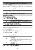
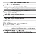
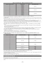
GPI input function list
[Group Select]
Signal name
Description
[Type]
[ME1], [ME2]
KEY1 ON to KEY4 ON
Executes the transition for KEY1 to
KEY4.
[LowEdge] or [HighEdge]
KEY1 CUT to KEY4 CUT
Executes the cut transition for KEY1 to
KEY4.
AUTO
Executes the auto transition.
CUT
Executes the cut transition.
[DSK]
KEY1 ON to KEY4 ON
Executes the cut transition for DSK1 to
DSK4.
[LowEdge] or [HighEdge]
KEY1 CUT to KEY4 CUT
Executes the cut transition for DSK1 to
DSK4.
[USK]
USK1 ON - USK4 ON
On/off of USK1 ON to USK4 ON.
[Low Edge] or [High Edge]
[OTHER]
No Assign
No function assigned
―
REC Still1 to REC Still4
Still recording
[LowEdge] or [HighEdge]
REC Clip1 to REC Clip4
Clip recording start
PLAY Clip1 to PLAY Clip4
Clip playback start
STOP Clip1 to STOP Clip4
Clip recording stop or playback stop
FTB
FTB transition start
Tally G1 DSBL
[Tally Group1] tally signal is not output
[LowLevel] or [HighLevel]
Tally G2 DSBL
[Tally Group2] tally signal is not output
Tally G3 DSBL
[Tally Group3] tally signal is not output
Tally G4 DSBL
[Tally Group4] tally signal is not output
[Macro]
Macro1-1 - Macro9-9
Playback of the applicable macro
register memory (one out of 1-1 to 9-9).
[Low Edge] or [High Edge]
Play Cancel
Canceling of the macro playback.
Play Resume
Resuming of the paused macro
playback.
@
@
NOTE
t
When a plug-in software application is introduced, there are cases where functions inherent to that application are added as functions to be assigned.
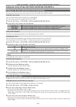
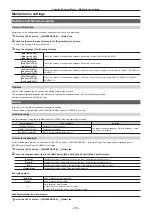
Setting the GPI output port
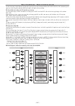
GPI output functions and tally outputs can be assigned and externally output through the GPI output port.
f
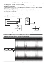
The GPI output ports are the pins 1 to 48 of the <GPI OUT1>/<GPI OUT2> terminal on the Main Frame AV-HS60U1/AV-HS60U2, and the pins 1 to 10
of the <GPI I/O> terminal on the Control Panel AV-HS60C1/AV-HS60C2/AV-HS60C4. (page 169)
1
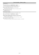
Select the <SYS> button
→
[PERIPHERAL]
→
[GPI OUT] tab.
Содержание AV-HS60C1E
Страница 5: ...Please read this chapter and check the accessories before use Chapter 1 Overview ...
Страница 32: ...This chapter describes basic operations and matters to be performed prior to use Chapter 4 Preparations ...
Страница 52: ...This chapter describes menu operations Chapter 5 Basic Operations ...
Страница 118: ...This chapter describes the input output signal settings Chapter 6 Input Output Signal Settings ...
Страница 129: ...This chapter describes how to operate the CONFIG menu displayed when the CONF button is pressed Chapter 7 CONFIG Menu ...
Страница 140: ...This chapter describes how to operate the system menu displayed when the SYS button is pressed Chapter 8 System Menu ...
Страница 162: ...This chapter describes the difference with the Standard mode Chapter 9 3G mode 4K mode ...
Страница 168: ...This chapter describes the terminals and signals of the unit Chapter 10 External Interfaces ...
Страница 173: ...This chapter describes the dimensions and specifications of this product Chapter 11 Specifications ...
Страница 184: ...This chapter describes the setting menu table and terms Chapter 12 Appendix ...
Страница 206: ...Web Site http www panasonic com Panasonic Corporation 2014 ...


