– 33 –
Chapter 4 Preparations — Turning power on/off
Turning power on/off
Turning power on
1
Set the <POWER> switches of the Main Frame AV‑HS60U1/AV‑HS60U2 and the Control Panel AV‑HS60C1/AV‑HS60C2/AV‑HS60C4
to <ON>.
f
For the redundant power supply model (AV-HS60U2, AV-HS60C2, AV-HS60C4), set both <POWER> switches of the power supply 1 and the power
supply 2 to <ON>.
f
The power indicator will light up when power is supplied.
Notification when the power is turned on for the first time
When using the products for the first time, connect the Control Panel AV‑HS60C1/AV‑HS60C2/AV‑HS60C4 to the <PANEL> terminal of the Main Frame
AV-HS60U1/AV-HS60U2, and then turn on the power.
Depending on the combination of the purchased Main Frame and the Control Panel, the version of the firmware for each may not match.
When the version of the firmware for the Main Frame and the Control Panel does not match, the Control Panel will not correctly boot when the power is
turned on.
Boot status when the versions do not match
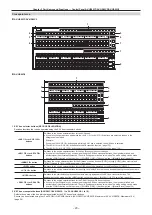
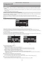
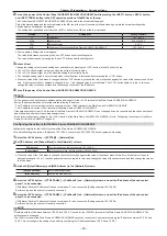
Two buttons out of PST/B bus crosspoint buttons in the ME line in front will blink. One button will blink in green, and the other will blink in red. (Fig. 1)
BUS
SHFT
Green
Red
Fig. 1
f
When it goes into this status, it is necessary to match the firmware version of the Control Panel to the Main Frame.
f
If it does not go into this status and the Control Panel boots normally, the firmware versions of the Main Frame and the Control Panel do match.
f
Check the latest software information and perform the version update of the software if necessary. For details, refer to “To perform the version update
of the software” (page 34).
r
To match the firmware version of the Control Panel to the Main Frame
The firmware of the Control Panel is updated when the following operation is performed. Once the update is correctly performed, the firmware version of
the Control Panel will match with the firmware version of the Main Frame, and it will boot in normal status.
RECALL
STORE
DEL
CHR
LIN
FULL
FULL
WIPE
01s00f
MIX
01s00f
MIX
01s00f
MIX
CG5V
CG6V
CAM1
CAM2
01s00f
MIX
ME2
01s00f
BUS
SHFT
4-1
4-3
4-2
4-4
4-6
4-5
4-7
4-9
4-8
OP
STILL1
BUS
SHFT
4
SDI
IN3
3
SDI
IN2
2
SDI
IN1
1
Black
12
11
10
SDI
IN9
9
SDI
IN8
SDI
IN11
SDI
IN10
8
SDI
IN7
7
SDI
IN6
6
SDI
IN5
5
SDI
IN4
Red
Red
Blue
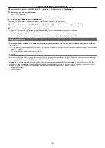
Fig. 2
Fig. 3
1
Press the button blinking in red (Fig. 1).
Update of the firmware is started.
f
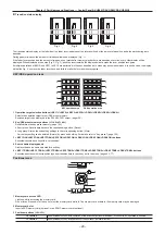
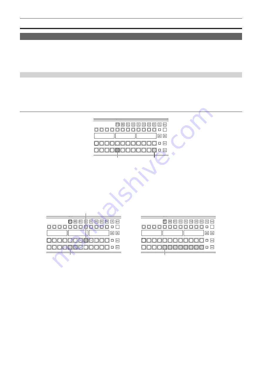
Status when the firmware of the Control Panel is being updated (Fig. 2)
- Eight buttons out of the PGM/A bus crosspoint buttons in the ME line in front will repeatedly blink in blue from left to right.
- Eight buttons out of the PST/B bus crosspoint buttons in the ME line in front will blink in red sequentially from left to right.
Update of the firmware will complete after approximately two minutes.
f
Status when the update of the firmware of the Control Panel is completed
- Eight buttons out of the PST/B bus crosspoint buttons in the ME in front will continue to blink in red. (Fig. 3)
-
Depending on the version of the firmware of the Main Frame, the Control Panel may automatically reboot. The firmware of the Control Panel is
updated correctly for this too.
2
Turn off the power of the Main Frame and the Control Panel.
f
Turn off the power after completing the update of the firmware of the Control Panel.
f
Do not turn off the power of the Main Frame and the Control Panel while the firmware of the Control Panel is still updating (Fig. 2).
3
Turn on the power of the Main Frame and the Control Panel.
Control Panel is booted and the menu screen is displayed in the menu panel when the firmware is correctly updated.
Содержание AV-HS60C1E
Страница 5: ...Please read this chapter and check the accessories before use Chapter 1 Overview ...
Страница 32: ...This chapter describes basic operations and matters to be performed prior to use Chapter 4 Preparations ...
Страница 52: ...This chapter describes menu operations Chapter 5 Basic Operations ...
Страница 118: ...This chapter describes the input output signal settings Chapter 6 Input Output Signal Settings ...
Страница 129: ...This chapter describes how to operate the CONFIG menu displayed when the CONF button is pressed Chapter 7 CONFIG Menu ...
Страница 140: ...This chapter describes how to operate the system menu displayed when the SYS button is pressed Chapter 8 System Menu ...
Страница 162: ...This chapter describes the difference with the Standard mode Chapter 9 3G mode 4K mode ...
Страница 168: ...This chapter describes the terminals and signals of the unit Chapter 10 External Interfaces ...
Страница 173: ...This chapter describes the dimensions and specifications of this product Chapter 11 Specifications ...
Страница 184: ...This chapter describes the setting menu table and terms Chapter 12 Appendix ...
Страница 206: ...Web Site http www panasonic com Panasonic Corporation 2014 ...


