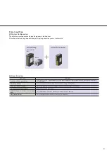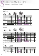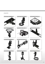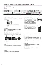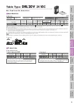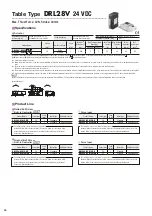
23
Fe
a
tu
re
s
H
o
w to R
e
a
d
S
p
e
cif
ications
T
a
ble
Sy
st
e
m
Configur
a
tion
Specifications and
Dimensions
Stan
d
a
rd
T
y
p
e
Specifications and
Dimensions
Gu
id
e
T
y
pe
Specifications and
Dimensions
Ta
b
le
Ty
p
e
Gen
e
ra
l
S
p
e
cif
ications
Specifications, Dimensions,
Connections
Dri
ve
r
Combination
List
A
c
ces
s
or
ies
Sele
c
tion
ca
lculation
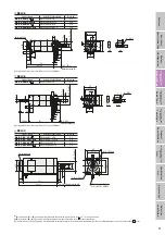
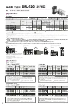
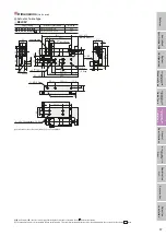
DRL42
Product Name
Actuator Product Name
Mass kg
DRL42-04B2MM-K
■
DRLM42-04B2MM-K
0.8
ϕ
14
1
5
23
31
±
0.3
31
±
0.3
42
0.3
16
9
6
6
2
42
6
119
±
2
86
±
1
(33)
ϕ
8
ϕ
25
−
0.021
(h7
)
0
UL Style 1430, AWG22
4
×
M4
×
8
Deep
M4
×
10
Deep
20
∼
60 (
Effective stroke
40)
2 Electromagnetic Brake Leads 600 mm
●
Comes with a connection cable (0.6 m). UL Style 3265, AWG22
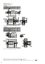
DRL60
Product Name
Actuator Product Name
Mass kg
DRL60-05
□
4P-K
■
DRLM60-05
□
4P-K
1.3
DRL60-05
□
4PN-K
■
DRLM60-05
□
4PN-K
1.35
ϕ
14
ϕ
26
ϕ
36
ϕ
36
−
0.025
(h7
)
0
(10.5)
8
98
±
1
108.5
±
2
10
1.5
8
50
±
0.3
60
50
±
0.3
12
60
A
A
ϕ
5.5
10
4
4
×
M5
A-A
M8
×
15
Deep
5 Motor Leads 600 mm
UL Style 3266, AWG22
24.5
∼
74.5 (
Effective stroke
50)
Adjusting Knob
●
A
(rolled ball screw) or
B
(ground ball screw) indicating the ball screw type is entered in the box
□
in the product name.
●
B
(pulse input) or
D
(built-in controller type) indicating the driver type is entered in the box
■
in the product name.
●
The dimensions of
apply to a configuration with an adjusting knob. For products without additional functions, the adjusting knob does not exist for the shaded
areas.

