41
Fe
a
tu
re
s
H
o
w to R
e
a
d
S
p
e
cif
ications
T
a
ble
Sy
st
e
m
Configur
a
tion
Specifications and
Dimensions
Stan
d
a
rd
T
y
p
e
Specifications and
Dimensions
Gu
id
e
T
y
pe
Specifications and
Dimensions
Ta
b
le
Ty
p
e
Gen
e
ra
l
S
p
e
cif
ications
Specifications, Dimensions,
Connections
Dri
ve
r
Combination
List
A
c
ces
s
or
ies
Sele
c
tion
ca
lculation
■
Connection and Operation (
Built-in controller type)
●
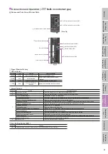
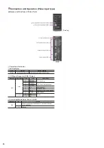
Names and Functions of Driver Parts
RS-485 Communication Connector (CN6)
RS-485 Communication Connector (CN7)
Terminal Resistance Switch (SW3)
[Driver Top]
Signal Monitor Indication
Not used (CN5)
Actuator Connector (CN4)
Power connector (CN1)
Control Module Connector (CN3)
Axis Setting Switch (SW1)
Function Switch (SW2)
I/O Signal Connector (CN2)
Signal Monitor Display
◇
LED Indicator
Indication
Color
Function
Lighting Condition
POWER
Green
Power supply indication
When the power supply is input
ALARM
Red
Alarm Indication
When a protective function is activated
(blinking)
C-DAT
Green
Communication Indication
When data is being received or sent
C-ERR
Red
Communication Error
Indication
When a communication error has occurred
◇
Alarm Contents
Blink Count
Function
Operating Condition
2
Overheat Protection
When the temperature in the driver reaches approximately 85˚C
3
Overvoltage Protection
When the internal voltage of the driver exceeds the permissible value
7
±
LS Simultaneous Input
When both
+
LS and
−
LS are detected
±
LS Reverse Connection
When the LS opposite from the home direction is detected during return-to-home operation
Return-to-Home Operation Abnormality
When the return-to-home sequence does not end normally
HOMES Not Detected
When HOMES is not detected from
+
LS to
−
LS during a return-to-home operation in 3-sensor mode
TIM, SLIT Signal Abnormality
When the TIM input or SLIT input is not detected during return-to-home operation
Hardware Overtravel
When
+
LS or
−
LS is detected
Software Overtravel
When the software limit is reached
Return-to-Home Operation Offset Abnormality
When
+
LS or
−
LS is detected in offset movement in a return-to-home operation
Operating Data Error
When an operating data error has occurred
RS-485 Communication Error
When the set number of RS-485 communication consecutive errors is reached
RS-485 Communication Timeout
When an RS-485 communication timeout is detected
Network Bus Error
When the bus goes OFF for the higher level network for the network controller during motor operation
Network Converter Error
When an alarm is issued in the network converter
9
EEPROM Error
When the saved driver data is damaged
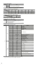
Axis Setting Switch (SW1)
Indication
Function
SW1
Set when using with RS-485 communication. Sets the axis number (Factory Setting: 0).


