46
■
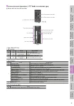
Connection and Operation (Pulse input type)
●
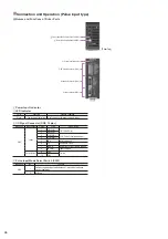
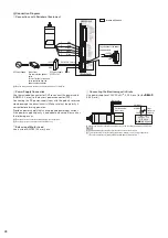
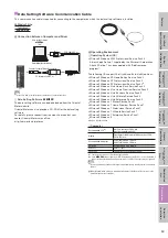
Names and Functions of Driver Parts
Pulse Input Mode Select Switch (SW2)
Resolution Setting Switch (SW1)
Power Input Indicator
I/O Signal Connector (CN3)
Actuator Connector (CN2)
Power connector (CN1)
[Driver Top]
Power Input Indicator
◇
LED Indicator
Color
Function
Lighting Condition
Green
Power supply indication
Lights up when the power supply is input.
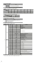
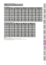
I/O Signal Connector (CN3, 10 pins)
Indication
Input/output
Pin No.
Code
Signal Name
CN3
Input
1
CW (PLS) +
CW Pulse (Pulse)
2
CW (PLS) −
3
CCW (DIR) +
CCW Pulse (Traveling direction)
4
CCW (DIR) −
5
AWO
All windings off
6
CS Resolution
Select
7
ACDOFF
Automatic current cutback release
8
IN-COM Input
common
Output power
9
TIM+
Timing
10
TIM−
Pulse Input Mode Select Switch (SW2)
Indication
No.
Function
SW2
1
Switches the pulse input mode between 1-pulse input mode and
2-pulse input mode.
2
Not used.

