42
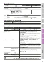
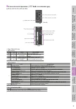
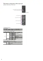
Function Switch (SW2)
Indication
No.
Function
SW2
1
Sets the RS-485 baud rate (Factory Setting: ON).
2
3
4
Sets the RS-485 connection destination (Factory Setting: OFF).
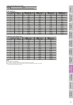
◇
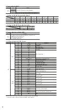
Settings for RS-485 Communication Speed
Baud Rate
No.
9600 bps
19200 bps
38400 bps
57600 bps
115200 bps
250000 bps
312500 bps
625000 bps
1
OFF
ON
OFF
ON
OFF
ON
OFF
ON
2
OFF
OFF
ON
ON
OFF
OFF
ON
ON
3
OFF
OFF
OFF
OFF
ON
ON
ON
ON
◇
Settings for RS-485 Connection Destination
Connection Destination
No.
Network Converter
General Purpose
Master Equipment
4
OFF
ON
Terminal Resistance Switch (SW3)
Indication
Function
SW3
Sets whether or not there is a terminating resistor (120
Ω
) for RS-485
communication (Factory Setting: OFF).
OFF: Terminating resistor not used
ON: Terminating resistor used
I/O Signal Connector (CN2, 40 pins)
Indication
I/O
Pin No.
Code
Signal Name
CN2
Input
A1
IN-COM0
Input common
A2
START
Start Input
A3
ALM-RST
Alarm Reset Input
A4
AWO
All Windings Off Input
A5
STOP
Stop Input
A6
M0
Data Selection Input
A7
M1
A8
M2
A9
M3
A10
M4
A11
M5
A12
HOME/P-PRESET
Return-to-Home/Position Preset Input
A13
FWD
CW Rotation (Forward) Input
A14
RVS
CCW (Reverse) Input
A15
+
LS
+
Side Limit Sensor Input
A16
−
LS
−
Side Limit Sensor Input
A17
HOMES
Mechanical Home Sensor Input
A18
SLIT
Slit Sensor Input
A19
−
−
A20
IN-COM1
Sensor Input Common
Output
power
B1
MOVE
+
Output During Actuator Drive
B2
MOVE
−
B3
ALM
+
Alarm Output
B4
ALM
−
B5
OUT1
+
Control Output 1
✽
B6
OUT1
−
B7
OUT2
+
Control Output 2
✽
B8
OUT2
−
B9
OUT3
+
Control Output 3
✽
B10
OUT3
−
B11
OUT4
+
Control Output 4
✽
B12
OUT4
−
B13
−
−
B14
−
−
B15
PLS-OUT
+
Pulse Output (Line driver output)
B16
PLS-OUT
−
B17
DIR-OUT
+
Traveling Direction Output (Line driver output)
B18
DIR-OUT
−
B19
GND
GND
B20
−
−
✽
Control outputs 1 (OUT1) to 4 (OUT4) set functions to be assigned according to parameter settings.
The initial values are OUT1 (AREA), OUT2 (READY), OUT3 (WNG), and OUT4 (HOME-P).

