OPTIMOD-AM DIGITAL
INSTALLATION
2-9
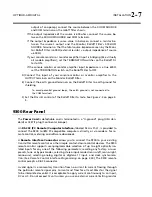
fessional and semi-professional audio equipment, balanced or unbalanced, hav-
ing a source impedance of 600
or less. The input is EMI suppressed.
Input connections are the same whether the driving source is balanced or unbal-
anced.
Connect the red (or white) wire to the pin on the XLR-type connector (#2 or #3)
that is considered
H
IGH
by the standards of your organization. Connect the black
wire to the pin on the XLR-type connector (#3 or #2) that is considered
L
OW
by
the standards of your organization.
In low RF fields (like a studio site), connect the cable shield at 9300 input only —
it should not be connected at the source end. In high RF fields (like a transmitter
site), also connect the shield to pin 1 of the male XLR-type connector at the 9300
input.
If the output of the driving unit is unbalanced and does not have separate
C
HASSIS
G
ROUND
and (–) (or
L
OW
) output terminals, connect both the shield and
the black wire to the common (–) or ground terminal of the driving unit.
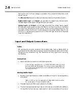
Analog Audio Outputs
There are two monophonic outputs (for two transmitters).
Electronically balanced and floating outputs simulate a true transformer output.
Because of the built-in high-order EMI suppression filter, the source impedance is
351
. The output is capable of driving loads of 600
or higher; the 100% modu-
lation level is adjustable with the AO 100% control over a –6dBu to +24dBu
range. Loading the output with 600
will decrease the output level by 4.0 dB
compared to a high impedance (bridging) load and will reduce the maximum
available output level by 4.0 dB. A software switch in Analog Output screen al-
lows the output level calibration to be set for a bridging or 600
load.
If an unbalanced output is required (to drive unbalanced inputs of other equip-
ment), it should be taken between pin 2 and pin 3 of the XLR-type connector.
Connect the
L
OW
pin of the XLR-type connector (#3 or #2, depending on your
organization’s standards) to circuit ground; take the
H
IGH
output from the re-
maining pin. No special precautions are required even though one side of the
output is grounded.
Use two-conductor foil-shielded cable (Belden 8451, or equivalent).
At the 9300’s output (and at the output of other equipment in the system), do
not connect the cable’s shield to the CHASSIS GROUND terminal (pin 1) on the
XLR-type connector. Instead, connect the shield to the input destination. Con-
nect the red (or white) wire to the pin on the XLR-type connector (#2 or #3) that
is considered
H
IGH
by the standards of your organization. Connect the black wire
Содержание OPTIMOD-AM 9300
Страница 1: ...Operating Manual OPTIMOD AM 9300 Digital Audio Processor Version 2 0 Software...
Страница 7: ...Operating Manual OPTIMOD AM 9300 Digital Audio Processor Version 2 0 Software...
Страница 178: ...3 46 OPERATION ORBAN MODEL 9300...
Страница 200: ......
Страница 221: ...OPTIMOD AM DIGITAL TECHNICAL DATA 6 21...
Страница 222: ...6 22 TECHNICAL DATA ORBAN MODEL 9300 CONTROL BOARD PARTS LOCATOR...
Страница 228: ...6 28 TECHNICAL DATA ORBAN MODEL 9300...
Страница 229: ...OPTIMOD AM DIGITAL TECHNICAL DATA 6 29 I O DSP BOARD LEFT AND RIGHT ANALOG INPUTS...
Страница 230: ...6 30 TECHNICAL DATA ORBAN MODEL 9300 I O DSP BOARD ANALOG OUTPUTS...
Страница 231: ...OPTIMOD AM DIGITAL TECHNICAL DATA 6 31...
Страница 238: ...6 38 TECHNICAL DATA ORBAN MODEL 9300 FRONT VIEW REAR VIEW FRONT PANEL PARTS LOCATOR DIAGRAM...
Страница 242: ...6 42 TECHNICAL DATA ORBAN MODEL 9300 NOTES...


