2-12
INSTALLATION
ORBAN MODEL 9300
Next
and
Prev
(
and
) buttons scroll the screen horizontally to accommo-
date menus that cannot fit in the available space. They also allow you to move
from one character to the next when you enter data into your 9300. These flash
when such a menu is in use. Otherwise, they are inactive.
Control Knob
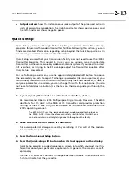
is used to change the setting that is selected by the soft buttons.
To change a value, you ordinarily have to hold down a soft button while you are
turning the control knob
.
Recall
button allows you recall a Factory or User Preset.
Selecting the Recall button does not immediately recall a preset. See step
16 on page 2-18 for instructions on recalling a preset.
Modify
button brings you to list of controls that you can use to edit a Factory or
User Preset. If you edit a Factory Preset, you must save it as a new User Preset to
retain your edit.
Setup
button accesses the technical parameters necessary to match the 9300 to
your transmission system.
Escape
button provides an escape from the currently active screen, returning
the user to the next higher-level screen. Repeatedly pressing
Escape
will always
return you to the Idle screen, which is at the top level of the screen hierarchy.
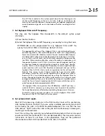
Input
meters show the peak input level applied to the 9300’s analog or digital
inputs with reference to 0 = digital full-scale. If the input meter’s red segment
lights up, you are overdriving the 9300’s analog to digital converter. This clips at
+27 dBu.
AGC
meter shows the gain reduction of the slow two-band AGC processing that
precedes the separate analog and digital processing chains. Full-scale is 25 dB
gain reduction. You can switch the meter so that it either reads the gain reduc-
tion of the Master (above-200 Hz) band, the Bass (below-200 Hz) band, or the
difference between the gain reduction in the Master and Bass bands.
The latter reading is useful for assessing the dynamic bass equalization
that the AGC produces and it helps you set the AGC BASS COUPLING con-
trol.
Gate
LED indicates gate activity, lighting when the input audio falls below the
threshold set by the AGC gate threshold control (via the Full Control screen’s
AGC
G
ATE
control). When this happens, the AGC’s recovery time is slowed to
prevent noise rush-up during low-level passages.
There is also an independent gate for the multiband compressor. You can
only see its action from the Optimod PC Remote software.
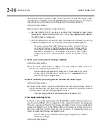
Gain Reduction
meters show the gain reduction in the multiband compressors.
Full-scale is 25 dB gain reduction.
Содержание OPTIMOD-AM 9300
Страница 1: ...Operating Manual OPTIMOD AM 9300 Digital Audio Processor Version 2 0 Software...
Страница 7: ...Operating Manual OPTIMOD AM 9300 Digital Audio Processor Version 2 0 Software...
Страница 178: ...3 46 OPERATION ORBAN MODEL 9300...
Страница 200: ......
Страница 221: ...OPTIMOD AM DIGITAL TECHNICAL DATA 6 21...
Страница 222: ...6 22 TECHNICAL DATA ORBAN MODEL 9300 CONTROL BOARD PARTS LOCATOR...
Страница 228: ...6 28 TECHNICAL DATA ORBAN MODEL 9300...
Страница 229: ...OPTIMOD AM DIGITAL TECHNICAL DATA 6 29 I O DSP BOARD LEFT AND RIGHT ANALOG INPUTS...
Страница 230: ...6 30 TECHNICAL DATA ORBAN MODEL 9300 I O DSP BOARD ANALOG OUTPUTS...
Страница 231: ...OPTIMOD AM DIGITAL TECHNICAL DATA 6 31...
Страница 238: ...6 38 TECHNICAL DATA ORBAN MODEL 9300 FRONT VIEW REAR VIEW FRONT PANEL PARTS LOCATOR DIAGRAM...
Страница 242: ...6 42 TECHNICAL DATA ORBAN MODEL 9300 NOTES...


